
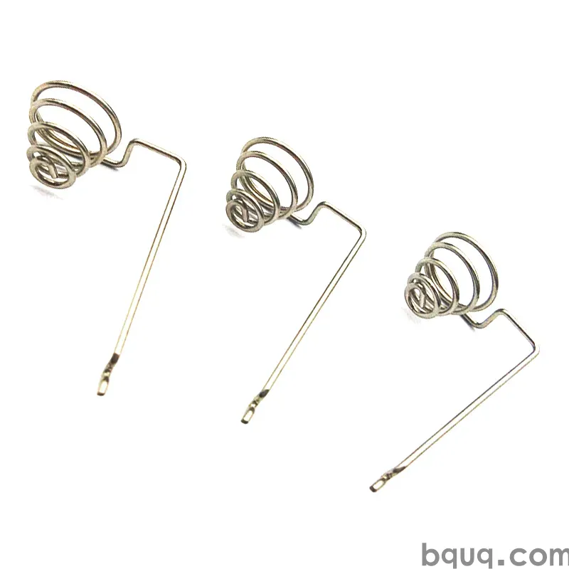
Stamped Reed Switch and Sensor Parts
Short answer: Stamped reed switch and sensor parts are thin-gauge metal components — reed blades, lead frames, contact pads, housings and mounting clips — produced on progressive dies from 0.05–0.50 mm strip. The critical parameters are blade flatness (typically 0.02 mm or better), contact gap consistency (±0.02 mm indicative), burr height under 0.02 mm, and controlled plating thickness on the contact zone. BQUQ stamps these parts on four production lines in one Dongguan ISO9001 factory, holds ±0.005 mm on CNC-machined die inserts, and returns a quote in 12 working hours with flexible MOQ.
Reed switches and small sensors look simple from the outside: a glass or plastic envelope, two or three metal blades, a couple of leads. Inside, the device lives or dies on metal parts that are stamped to tolerances most people never see. A reed switch that fails after 200,000 operations usually did not fail because of the glass. It failed because a blade was 0.03 mm out of flat, because the contact plating was 0.4 µm thin on one side, or because a burr on a lead frame edge released a particle into the gap.
This article covers what buyers and design engineers should specify when sourcing stamped reed switch parts and sensor components, how the stamping process is controlled, and where the real cost and quality trade-offs sit.
What counts as a "stamped reed switch part"?
The reed switch itself is an assembly, but most of its metal content is stamped. Typical stamped parts in this family include:
- Reed blades — flat, thin, ferromagnetic blades (usually nickel-iron alloy) that flex to close the contact gap.
- Contact pads / contact rivets — precious-metal or plated contact zones, sometimes stamped as a coined pad on the blade itself.
- Lead frames — the carrier strip that holds blades, leads and sometimes the glass envelope during assembly.
- Sensor terminals and pins — the electrical interface for Hall-effect, reed, inductive and optical sensor packages.
- Housings, brackets and mounting clips — stamped sheet metal that positions the sensor in the final product.
In high-volume production these parts are almost always made on a progressive die, where the strip is fed through a sequence of stations: blanking, piercing, coining, forming, and sometimes in-die assembly or separation.
Why the reed blade is the hardest part
A reed blade has to do three things at once: flex repeatably, carry current, and sit in a precise position inside the envelope. That combination drives the tolerance stack:
| Blade feature | Typical requirement | Why it matters |
|---|---|---|
| Thickness | 0.10–0.25 mm, ±0.01 mm | Sets spring rate and pull-in sensitivity |
| Flatness | 0.02 mm or better | Prevents gap drift over life |
| Camber / bow | < 0.05 mm per 10 mm | Keeps the gap parallel |
| Burr height | < 0.02 mm | Avoids particle generation and shorting |
| Contact zone plating | 0.5–3.0 µm Au or Ag, controlled | Contact resistance and wear |
| Blade length | ±0.05 mm typical | Pull-in ampere-turn consistency |
Those numbers are indicative for small signal reed switches. Higher-reliability or higher-frequency parts tighten them further, and the tooling cost follows.
How is a stamped reed switch part actually produced?
The process is a chain, and every link can move the final tolerance.
1. Strip selection and incoming control
Reed blades are usually nickel-iron (NiFe) alloys such as 52 alloy or 42 alloy, chosen for a predictable coefficient of thermal expansion and magnetic permeability. Sensor terminals are more often brass, phosphor bronze, beryllium copper or copper-nickel-silicon. Thickness tolerance on the incoming coil is the first place accuracy is won or lost — a coil that varies ±0.015 mm across its width will produce blades that vary in spring rate no matter how good the die is.
2. Die design and insert machining
The die sets the geometry. For reed blades, the critical stations are the blanking profile, the coining or embossing station that sets the contact pad, and any forming station that introduces a controlled bend. Die inserts and punches are often wire-EDM cut and then finished on a CNC machining centre to ±0.005 mm, which is what BQUQ does in-house so that die corrections do not wait on an outside vendor.
3. Stamping and in-die monitoring
A well-run progressive stamping line for reed parts runs with:
- Strip feeding accuracy of ±0.01 mm or better
- Tonnage or force monitoring on the coining and blanking stations
- Regular first-off and in-process dimensional checks
- Controlled lubrication, because oil film thickness changes the coin depth
4. Plating and post-processing
Plating is where many reed and sensor parts quietly go wrong. Gold, silver, palladium-nickel and tin all behave differently on thin strip, and the contact zone often needs selective or spot plating rather than full-surface plating. Masking, barrel plating versus reel-to-reel plating, and the risk of plating into a burr are all real variables — the same issues covered in stamped spring contact plating.
5. Separation, cleaning and packaging
Parts that are separated in-die arrive clean and untangled. Parts that are tumbled or vibratory-finished can pick up media dust and edge damage. For reed blades, packaging flatness matters as much as manufacturing flatness: a blade that is perfect at the press can be bent by a careless bag.
Tolerance and capability: what should a buyer actually specify?
The most common sourcing mistake is over-specifying everything. Tightening a tolerance that does not affect function raises tooling cost, slows the press, and increases the scrap rate without improving the device.
| Parameter | Loose / non-critical | Functional / specify this | Cost driver |
|---|---|---|---|
| Blade length | ±0.10 mm | ±0.05 mm | Die accuracy, strip feed |
| Blade flatness | 0.05 mm | 0.02 mm | Straightening, coining, handling |
| Burr height | < 0.05 mm | < 0.02 mm | Die maintenance interval |
| Plating thickness | ±50% | ±20% on contact zone | Plating method, masking |
| Contact gap (assembled) | ±0.05 mm | ±0.02 mm | Blade + envelope stack |
| Surface finish on contact | As-stamped | Controlled, no roll-over burr | Coining station design |
A practical rule: specify tight tolerances only on the two or three features that the device's electrical performance depends on. Everything else should be "as-stamped, burr-controlled."
Where ±0.005 mm fits
±0.005 mm is a realistic CNC machining tolerance for die inserts, punches, and gauges — not a blanket stamping tolerance. It matters because it determines how precisely the die can be corrected when a run drifts. A die that can only be adjusted in 0.02 mm steps will always produce parts that scatter more than a die adjustable in 0.005 mm steps. More on this in high-precision stamping tolerances.
Materials and plating for reed and sensor contacts
| Material | Typical use | Notes |
|---|---|---|
| 52 alloy / 42 alloy (NiFe) | Reed blades | Matched thermal expansion, magnetic response |
| Phosphor bronze | Sensor terminals, springs | Good fatigue life, moderate conductivity |
| Beryllium copper | High-cycle sensor springs | Best fatigue, needs careful handling |
| Brass | General terminals, brackets | Low cost, easy plating |
| Copper-nickel-silicon | Precision terminals | Good strength + conductivity balance |
| Stainless steel 301/304 | Housings, clips, brackets | Corrosion resistance, spring temper options |
Plating choices follow the contact physics. Gold is standard for low-level signal contacts where oxide films would break the circuit. Silver gives lower resistance but sulfides in the environment. Tin is cheap and solderable but forms whiskers over time. Palladium-nickel sits between gold and silver on cost and performance.
Inspection: how do you prove the parts are good?
Reed and sensor parts are small, thin and easily damaged by measurement itself. Good inspection plans combine:
- Optical / vision measurement for profile, gap and burr, non-contact
- Force-displacement testing on a sample basis to confirm spring rate
- Plating thickness by XRF at defined points on the contact zone
- Flatness on a granite surface plate or by laser scan
- Functional pull-in / drop-out testing on assembled samples where the customer allows it
Sampling frequency should be tied to the process, not to a calendar. A stable press running a mature die might need hourly checks; a new die running a new alloy needs far more until capability is demonstrated.
Cost, MOQ and lead time realities
Stamped reed and sensor parts are usually high-volume items, but not always. Design engineers prototyping a sensor often need 500 pieces, not 500,000. The economics are driven by tooling, not by piece price:
- Tooling is the dominant upfront cost. A simple 3–5 station progressive die for a bracket is modest; a 10–15 station die with coining, in-die assembly and selective plating features is a serious investment.
- Piece price falls steeply with volume because press time is fixed per stroke.
- MOQ can be flexible when the die already exists or when the part can be run on a shared die platform.
- Lead time splits into tooling lead time and production lead time. Tooling usually dominates.
BQUQ quotes in 12 working hours and runs four production lines in one Dongguan factory, so a reed blade, its lead frame, and the mounting bracket can be sourced together rather than from three vendors with three tolerance stacks.
Design rules that prevent expensive problems
A short checklist before you release a reed or sensor stamping drawing:
1. Keep the contact pad on a single plane — avoid forming through the contact zone.
2. Put a generous radius on every bend; sharp inside corners crack in NiFe alloys.
3. Specify burr direction and burr height, not just "deburr."
4. Avoid narrow necks between the carrier strip and the part where the strip must survive coining.
5. Define the datum for flatness measurement — otherwise the measurement is not reproducible.
6. State plating thickness on the contact zone separately from the rest of the part.
7. Ask for a first-article inspection report with actual numbers, not just pass/fail.
Frequently Asked Questions
Q: What is the tightest tolerance achievable on stamped reed switch blades?
A: On thin NiFe strip, ±0.02 mm on blade length and 0.02 mm flatness are realistic production tolerances, with tighter values possible on selected features at higher cost. The die inserts themselves can be machined to ±0.005 mm, which gives the correction headroom to hold the part tolerance. Anything tighter than ±0.01 mm on a stamped blade should be justified by measured device performance, not by habit.
Q: Which material is best for reed switch blades?
A: Nickel-iron alloys such as 52 alloy are the standard choice because their coefficient of thermal expansion matches the glass envelope and their magnetic permeability gives predictable pull-in behaviour. Thickness typically runs 0.10–0.25 mm. For sensor terminals and springs, phosphor bronze or beryllium copper is usually better because fatigue life and conductivity matter more than magnetic response.
Q: How do you control burrs on small stamped sensor contacts?
A: Burr control starts in the die: correct punch-to-die clearance, sharp cutting edges, and a maintenance interval based on stroke count rather than on visible wear. A coining or shaving station can flatten or remove the roll-over burr. In-process vision inspection then confirms burr height, typically held under 0.02 mm for reed and sensor parts where loose particles would cause intermittent contact.
Q: Can reed blades and lead frames be stamped in one progressive die?
A: Yes, and it is often the better approach. Running blades, lead frames and any small bracket in one die keeps the tolerance relationship between them consistent, reduces handling, and cuts the number of incoming inspection points. The trade-off is a more complex die and a longer tooling lead time, which only pays back at meaningful volume.
Q: What plating should be specified for low-level signal contacts?
A: Gold over nickel is the usual answer for low-level signals because it resists oxide and sulfide film formation. Thickness is commonly 0.5–1.5 µm gold over 1–2 µm nickel, applied selectively to the contact zone to control cost. Silver is an alternative where contact resistance matters more than environmental stability, but it needs a controlled atmosphere or a barrier layer.
Related Resources
- About BQUQ and our Dongguan factory: /about/
- Custom metal stamping capabilities: /custom-metal-stamping/
- Stamped terminals and contacts: /stamping-terminals-contacts/
- Stamped brackets and mounts: /stamping-brackets-mounts/
- Industry trends: /industry-dynamics/
- Technical articles: /bquq-blog/
- FAQ and case studies: /faq/ | /case/
Authored by the BQUQ Engineering Team. BQUQ (Dongguan) runs CNC machining (±0.005 mm), metal stamping, custom springs, and heat sink production in one ISO9001 factory. Source-direct from Dongguan, China — quote in 12 hours: sc@bquq.com | WhatsApp +86 13713157787 | www.bquq.com


