
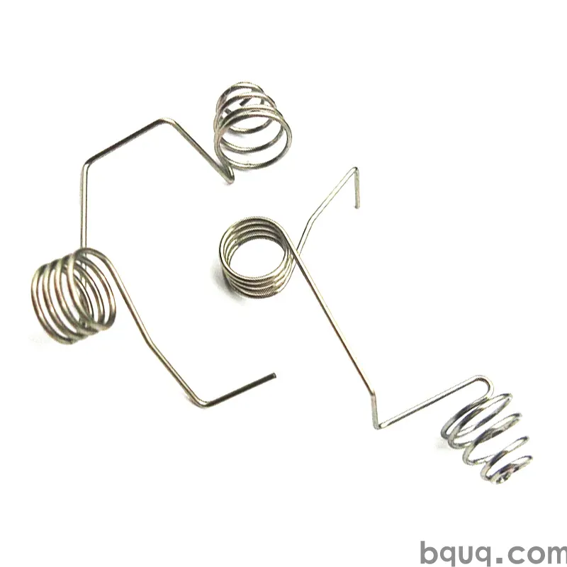
Cam Piercing and Forming: Features a Straight Press Cannot Make
Short answer: A straight vertical press can only punch and bend in the direction of ram travel. Cam piercing and cam forming add a sliding wedge-driven tool inside the die that converts vertical ram motion into horizontal or angled motion, so you can pierce side walls, notch inside a return flange, and form bends that face sideways or undercut the part. Typical cam units handle 15° to 60° of working angle and add roughly 10–25% to die cost, but they eliminate secondary operations, extra fixtures, and re-registration error. If your part has a hole in a vertical wall, a louver, a side lance, or a bend whose axis is not parallel to press travel, a cam is usually the only single-hit answer.
Why a straight press hits a wall
Every conventional stamping die inherits one hard constraint: the ram moves up and down, and so does everything rigidly bolted to it. Punches travel vertically. Bending inserts rotate about horizontal axes. Material feeds horizontally through the die.
That works beautifully for flat parts and for bends whose axis is perpendicular to ram travel. It fails the moment a feature points sideways.
Consider a drawn or formed bracket with a 4 mm wall standing 8 mm tall. The customer wants a 2.5 mm hole through that wall, positioned 3 mm off the base. A vertical punch cannot reach it — the punch would have to pass through the wall's top edge and would shear the wall instead of piercing it. The same problem appears with:
- Louvres and vents punched into a side wall
- Notches on the inside of a return flange
- Holes in a hemmed or curled edge
- Bends whose axis is vertical, so the flange folds sideways
- Undercuts that a vertical forming punch cannot release from
- Side lances and tabs used as locating features for downstream assembly
Historically these features were made in a second operation: a separate die, a manual fixture, a drilled hole, or a CNC milled slot. Each of those adds handling, re-registration tolerance stack-up, and cost per piece. Cam tooling moves the feature back into the main die and back into one hit.
What a cam unit actually does
A cam unit is a mechanical motion converter. It has three functional parts:
1. The driver (wedge or horn) — mounted on the upper shoe, it descends with the ram.
2. The slide (cam block) — mounted on a wear plate in the lower die, it carries the working tool (punch, insert, or forming steel).
3. The return system — a spring, nitrogen cylinder, or positive return that pushes the slide back to its rest position on the upstroke.
As the driver descends, its angled face contacts the slide's matching angled face. The angle converts vertical force into a horizontal or angled stroke. A 45° cam face produces roughly a 1:1 force ratio; a 30° face produces more slide travel per unit of ram travel but multiplies side load and friction.
The working tool then does its job — piercing, notching, lancing, or forming — while the slide is fully extended and supported against a back-up block. On the upstroke, the return system retracts the slide so the strip can feed.
The critical support detail
A cam slide must be backed up at full extension. If the slide is cantilevered when the punch contacts the material, the side thrust will deflect it, and you get a tapered hole, a broken punch, or a galling wear plate. Good cam design puts a hardened back-up block directly behind the slide at the bottom of the stroke, so the piercing force is carried in compression rather than in bending.
Cam piercing vs. cam forming vs. cam flanging
These three are often lumped together, but the tooling and the design rules differ.
| Feature | Motion type | Typical tool material | Key design limit |
|---|---|---|---|
| Cam piercing | Horizontal or angled punch stroke | M2 / SKD11 / powder metal punch | Punch must clear the wall on retract; slug evacuation path |
| Cam notching / lancing | Horizontal shear | SKD11 insert | Shear angle and strip support |
| Cam forming / flanging | Angled bend, often 15°–60° | Die steel forming insert | Springback compensation; bend radius vs. material thickness |
| Cam bending (rotary) | Rotating insert about a pivot | Hardened pivot pins + inserts | Rotation clearance and cam return timing |
| Cam coining / embossing | Short angled stroke, high tonnage | Carbide or PM steel | Tonnage per unit area; slide rigidity |
The unifying rule: the more the cam angle deviates from vertical, the more side thrust you generate, and the more robust the slide and back-up must be.
Design rules that keep cam dies alive
Keep the cam angle between 15° and 60°
Below about 15° from horizontal you get very little slide travel for a lot of ram travel, and the wedge faces tend to gall. Above about 60° the mechanical advantage collapses and side loading climbs steeply. The 30°–45° band is the practical sweet spot for most progressive dies.
Size the slide for the side load, not the punch
A 2 mm punch in 1.0 mm mild steel needs modest force. But the cam slide also absorbs friction, return-spring preload, and any misalignment. Design the slide cross-section so bearing stress on the wear plate stays well under the plate's rated load. Under-designed slides wear oval and lose position within a few hundred thousand strokes.
Give the slug somewhere to go
Cam piercing produces a slug that must exit horizontally. If the slug can't fall free, it will ride the punch back into the die and cause a double-hit, a broken punch, or a mark on the next part. Plan a slug chute, an air blast, or a drop-through window in the lower shoe. This is one of the most common causes of cam die failure in the field.
Match return force to slide mass and stroke
The return system must fully retract the slide before the strip feeds. If retraction is slow or incomplete, the strip will crash into the extended punch. Nitrogen cylinders give more consistent force than coil springs and are preferred where cycle rates are high or the slide is heavy.
Control the timing window
The cam must be fully extended before the punch contacts material, and fully retracted before feed begins. In a progressive die this timing is set by the ram position and the feed cam. Build in a small safety margin — typically a few degrees of crank rotation — rather than designing to the theoretical limit.
Plan for maintenance access
Cam units wear. Wear plates, return springs, and punches need replacement. A cam that can only be serviced by pulling the entire die set out of the press will cost you production hours every time. Design removable cam cartridges where the part volume justifies it.
When a cam is the wrong answer
Cam tooling is not free. It adds die height, die cost, and maintenance items. Before committing, check whether one of these alternatives is cheaper:
| Situation | Better alternative | Why |
|---|---|---|
| Low volume (under ~5,000 pcs) | Secondary drill or laser op | Cam die cost never amortizes |
| Feature can be reoriented 90° | Redesign part so hole is in the flat | Zero added tooling |
| Simple side hole in a thick wall | CNC secondary op | Cam force too high for the wall |
| Very deep side draw | Deep draw then trim | Cam stroke becomes impractical |
| Tolerance tighter than ±0.05 mm on the side feature | Reorient or add a finishing op | Cam slides stack tolerance |
If the part is a stamped terminal, contact, or bracket with a side lance, a cam is usually justified because the volumes are high and the feature is functional. If the part is a low-volume enclosure panel, it usually is not.
How cam tooling changes your tolerance stack
A vertical pierce in a well-built die can hold ±0.02 mm on hole position relative to the die datum. A cam pierce adds sources of variation:
- Slide-to-wear-plate clearance
- Wear plate flatness and wear over life
- Driver-to-slide contact repeatability
- Return system seating repeatability
- Thermal growth in a long run
In practice, a well-maintained cam pierce holds roughly ±0.05 mm on position relative to the part datum, and that is the number to design around. If your print calls for ±0.02 mm on a cam-pierced hole, expect to add an inspection step or a secondary operation. See our notes on high-precision stamping tolerances for how these stacks are typically managed.
Cost and run-rate reality
Cam stations slow the die. Slide travel takes ram travel, and the timing window constrains how fast you can run. Expect a cam station to reduce strokes per minute by roughly 10–30% compared with an all-vertical die of the same size, depending on stroke length and cam angle.
Die cost impact is typically 10–25% for one or two cam stations, and more if the cams require custom cartridges, slug evacuation hardware, or nitrogen return systems. That premium is usually recovered quickly when it replaces a secondary operation. Our breakdown of stamping run rate economics walks through how to compare the two paths with real numbers.
What to send for a cam tooling quote
To quote cam piercing and forming accurately, a stamping supplier needs:
- 2D print with the side feature called out in a section view, not just a plan view
- 3D model if available — cam features are much easier to read in 3D
- Material grade, thickness, and temper
- Annual volume and expected die life
- Tolerance callouts on the cam-pierced feature specifically
- Any assembly constraints that fix the feature's position
Missing the section view is the single most common reason a cam quote comes back wrong or slow. A plan view of a side hole shows a circle; it does not show which wall the hole passes through or how far the punch must travel.
Where BQUQ fits
BQUQ runs four production lines in one Dongguan factory under ISO9001, covering progressive die stamping, CNC machining to ±0.005 mm, custom springs, and heat sink production. Cam piercing and cam forming are built into our progressive dies for terminals, contacts, brackets, and mounts — the parts where a side feature is functional rather than cosmetic. MOQ is flexible, and quotes come back within 12 working hours. If you are unsure whether a feature needs a cam or can be redesigned flat, send the print and we will tell you which is cheaper. Start with custom metal stamping or go straight to stamped terminals and contacts and stamped brackets and mounts for typical cam-tooled part families. If you are new to the process, metal stamping first article explains what the first-off inspection covers.
Frequently Asked Questions
Q: What is cam piercing in metal stamping?
A: Cam piercing uses a wedge-driven sliding tool inside the die to convert the press ram's vertical motion into a horizontal or angled punch stroke. This lets the die pierce holes in vertical side walls, inside return flanges, or on any surface a straight vertical punch cannot reach. It eliminates a secondary drilling or milling operation and keeps the feature in a single press hit.
Q: What angle should a cam slide be designed at?
A: Most cam units work best between 30° and 45° from horizontal. Below roughly 15° you get very little slide travel per unit of ram travel and the wedge faces tend to gall. Above about 60° the mechanical advantage drops and side loading on the slide rises sharply. The 30°–45° band balances travel, force, and slide rigidity.
Q: How much tolerance can a cam-pierced hole hold?
A: A well-maintained cam pierce typically holds about ±0.05 mm on position relative to the part datum. That is looser than a vertical pierce, which can hold around ±0.02 mm, because the cam adds slide clearance, wear plate variation, and return seating variation to the stack. If your print needs tighter, plan a secondary operation or redesign the feature.
Q: Does cam tooling slow down the stamping press?
A: Yes, typically by 10–30% compared with an all-vertical die of similar size. The slide needs ram travel to extend and retract, and the timing window between full extension and feed start constrains strokes per minute. The trade-off is usually still favorable because the cam replaces a separate secondary operation with its own handling and labor cost.
Q: When should I avoid cam piercing and use a secondary operation?
A: Below roughly 5,000 pieces per year, the cam die premium rarely amortizes, so a secondary drill, laser, or CNC operation is usually cheaper. Also avoid cams when the side wall is very thick, when the required side stroke is impractically long, or when the feature tolerance is tighter than the cam slide can repeatably hold.
Related Resources
- About BQUQ and our Dongguan factory: /about/
- Custom metal stamping capabilities: /custom-metal-stamping/
- Stamped terminals and contacts: /stamping-terminals-contacts/
- Stamped brackets and mounts: /stamping-brackets-mounts/
- Industry trends in stamping and tooling: /industry-dynamics/
- Technical articles library: /bquq-blog/
- Frequently asked questions: /faq/
- Case studies: /case/
- Contact the engineering team: /contact/
Authored by the BQUQ Engineering Team. BQUQ (Dongguan) runs CNC machining (±0.005 mm), metal stamping, custom springs, and heat sink production in one ISO9001 factory. Source-direct from Dongguan, China — quote in 12 hours: sc@bquq.com | WhatsApp +86 13713157787 | www.bquq.com


