
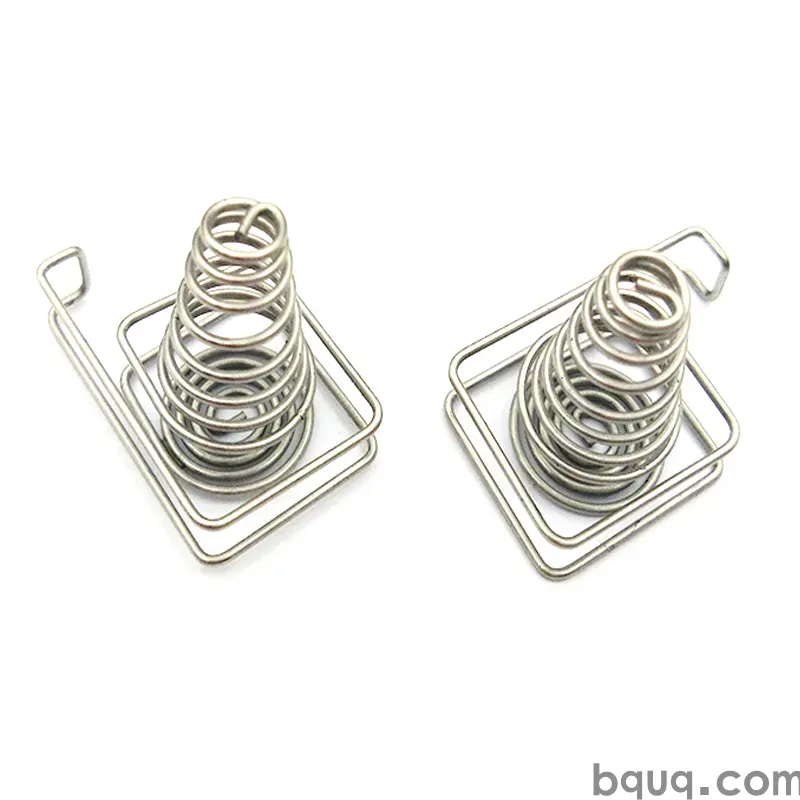
Stamped Heat Sink Fins: Zipper and Folded Fin Design
Short answer: Stamped heat sink fins are made two ways. Zipper fins are punched as a flat strip with interlocking tabs, then folded into a dense fin stack and bonded to a base — giving 1.0–1.5 mm fin pitch with high surface density. Folded (serpentine) fins are formed from one continuous strip folded back and forth, typically 1.5–3.0 mm pitch, with no bonding step. Both use aluminium or copper strip at 0.2–0.8 mm thickness, held to roughly ±0.05 mm on fin height and ±0.1 mm on pitch. BQUQ stamps both profiles in progressive dies in Dongguan and quotes in 12 working hours.
Why Stamped Fins Instead of Extruded or Die-Cast Heat Sinks?
Extruded heat sinks are the default for low-cost natural convection, but they hit a wall. An extrusion die can realistically produce a fin thickness-to-height ratio of about 1:8 to 1:13 depending on alloy and how brave your extruder is. Push past that and the fins tear or the die wears out. That caps you at roughly 1.5–2.0 mm fins on a 15–20 mm height, which is fine for a 30 W LED module and hopeless for a 150 W inverter stage.
Stamped fins break that ratio limit. Because the fin is formed from thin strip rather than pushed through a die, you can run 0.3 mm fins at 20 mm height — a ratio of about 1:66. That is a different class of surface area per unit volume.
The trade-off is a bonding or assembly step. Stamped fin stacks are not monolithic; the fins must be joined to a base plate or heat pipe. That joint is where most field failures originate, so it deserves as much design attention as the fin geometry itself.
| Attribute | Extruded | Die-cast | Stamped zipper/folded |
|---|---|---|---|
| Typical fin thickness | 1.5–3.0 mm | 1.5–2.5 mm | 0.2–0.8 mm |
| Typical fin pitch | 3–8 mm | 4–10 mm | 1.0–3.0 mm |
| Fin height limit | ~13× thickness | ~8× thickness | ~60× thickness |
| Tooling cost | Medium | High | Low–medium |
| Tooling lead time | 4–8 weeks | 6–12 weeks | 2–5 weeks |
| Best fit | Low-cost natural convection | Structural housings | Dense forced-air, heat pipes |
For a deeper comparison of when casting wins and when stamping wins, see metal stamping vs die casting.
What Is a Zipper Fin Heat Sink?
A zipper fin heat sink starts life as a flat stamped strip. The die punches the fin outline, plus a set of interlocking tabs along one or both edges — the "teeth" that give the design its name. The strip is then folded in a zipper pattern so each fin stands upright and its tabs engage the neighbouring fin.
The result is a self-supporting fin block. Fins stay parallel and evenly spaced without a separate spacer, because the tabs set the pitch mechanically. That is the key advantage: pitch accuracy comes from the tool, not from assembly skill.
Zipper fin geometry rules
- Fin pitch: 1.0–1.5 mm is achievable but demands clean shearing and good strip flatness. 1.5–2.5 mm is the comfortable production band.
- Fin thickness: 0.2–0.5 mm aluminium, 0.15–0.4 mm copper. Thinner fins raise surface area but reduce stiffness and make the fold line prone to cracking.
- Tab engagement: tabs should overlap by at least 0.3 mm. Under that, the stack can splay during handling.
- Fold radius: keep the inner radius at or above 0.5× strip thickness. Tighter radii cause orange-peel cracking on 6061 and work-hardened copper.
- Fin height: 8–35 mm typical. Beyond 35 mm the unsupported fin tips become vibration-sensitive.
Where zipper fins win
Zipper fins are the right answer when you need maximum surface area in a fixed footprint and you have a bonding process you trust — epoxy, solder reflow, or a swaged base. They are common in telecom remote radio heads, high-power LED arrays, and server DIMM cooling where fin pitch is the dominant thermal lever.
What Is a Folded Fin Heat Sink?
A folded fin (also called serpentine or accordion fin) heat sink is formed from a single continuous strip folded back and forth into a pleated stack. There are no separate fins and no tab engagement — the strip itself is the fin, and the folds set the pitch.
This is the design to choose when you want to eliminate the bonding step for the fin-to-fin joint. The stack is one piece, so there is no risk of a fin debonding from its neighbour. You still need to attach the stack to a base or heat pipe, but you have removed one failure mode.
Folded fin geometry rules
- Fin pitch: 1.5–3.0 mm. Folded fins rarely go below 1.5 mm because the fold radius consumes pitch budget.
- Fin thickness: 0.15–0.4 mm. Thinner strip folds more cleanly but flattens under compression.
- Fold radius: 0.4–0.8× strip thickness. This is the single most important variable — too tight and the fold cracks, too loose and you waste pitch.
- Fin height: 6–40 mm. Folded fins tolerate taller stacks than zipper fins because the continuous strip adds stiffness.
- Base interface: usually a flat foot on the bottom fold, soldered or thermally bonded to the base plate.
| Parameter | Zipper fin | Folded fin |
|---|---|---|
| Fin pitch range | 1.0–2.5 mm | 1.5–3.0 mm |
| Strip thickness | 0.2–0.5 mm | 0.15–0.4 mm |
| Fin-to-fin joint | Stamped tabs | Continuous strip |
| Bonding to base | Required | Required |
| Pitch accuracy driver | Die tab geometry | Fold tool radius |
| Best for | Highest surface density | Robustness, fewer joints |
Material Selection for Stamped Fins
Aluminium 1050, 1100, and 6061 are the workhorses. 1050 and 1100 offer the best thermal conductivity and the easiest folding, but they are soft and dent easily during handling. 6061 is stiffer and machines better at the base interface, at the cost of roughly 15–20% lower conductivity.
Copper (C11000, C10200) roughly doubles conductivity but triples material cost and work-hardens aggressively at the fold line. If you specify copper, expect to anneal between forming stages or accept a larger fold radius.
| Alloy | Thermal conductivity (W/m·K) | Formability | Relative cost | Typical use |
|---|---|---|---|---|
| Al 1050 | ~230 | Excellent | Low | Folded fins, high-density stacks |
| Al 1100 | ~220 | Excellent | Low | General stamped fins |
| Al 6061 | ~170 | Good | Low–medium | Stiff stacks, structural bases |
| Cu C11000 | ~390 | Fair | High | Premium thermal, tight budgets of space |
| Cu C10200 | ~390 | Fair | High | Heat pipe fin stacks |
For strip temper and coil-width decisions that affect fin flatness, see stamping coil material selection.
Tooling and Die Design for Fin Stamping
Fin stamping is a progressive-die job. A typical zipper fin die runs 6–12 stations: pilot, notch, fin profile blank, tab form, fold-line coining, cut-off, and often an in-die fold or a separate fold fixture downstream.
Three tooling points decide whether the part works:
1. Shear quality on the fin edge. A burr on a 0.3 mm fin is a measurable fraction of the fin thickness. It disturbs airflow and, worse, creates a stress riser at the fold. Keep die clearance at 5–8% of strip thickness for aluminium.
2. Fold-line coining. A shallow coined groove along the fold line localises the bend and prevents the bend from wandering. Without it, folded fins drift in pitch by 0.2–0.4 mm across a 100 mm stack.
3. Strip flatness control. Any coil camber transfers directly into fin lean. Specify camber under 1 mm per metre and verify incoming coil, not just finished parts.
Die maintenance matters more here than on a simple bracket. Fin edges are long, thin, and unforgiving. A worn punch that would pass on a 2 mm bracket will produce torn fin edges at 0.3 mm. Plan for preventive maintenance intervals based on stroke count, and track burr height as a leading indicator. Tooling cost structure for this class of die is covered in stamping tooling cost breakdown.
DFM Checklist for Stamped Heat Sink Fins
Run this before you release drawings.
- Fin thickness ≥ 0.15 mm; ≥ 0.2 mm preferred for handling.
- Fin pitch ≥ 1.0 mm for zipper, ≥ 1.5 mm for folded.
- Fold radius ≥ 0.4× strip thickness (zipper ≥ 0.5×).
- Fin height-to-thickness ratio under 60:1 for production stability.
- Tab overlap ≥ 0.3 mm on zipper fins.
- Burr height specified, typically ≤ 0.05 mm on fin edges.
- Base interface flatness called out separately — 0.05–0.1 mm typical.
- Bonding method named (epoxy, solder, swage) with a stated thermal resistance target.
- Coil temper and camber specified, not left to the supplier.
- A first-article inspection plan covering pitch, height, and burr.
BQUQ stamps fin profiles, brackets, and mounting hardware for these assemblies on four production lines in one Dongguan factory, with CNC machining at ±0.005 mm available when a base plate or heat pipe interface needs tighter tolerance than stamping can hold. Custom fin profiles are quoted in 12 working hours with flexible MOQ, so a 500-piece thermal prototype does not require a production-volume commitment.
Frequently Asked Questions
Q: What is the difference between a zipper fin and a folded fin heat sink?
A: A zipper fin heat sink is built from a flat stamped strip with interlocking tabs; the strip is folded so the tabs engage and set the fin pitch mechanically. A folded fin heat sink is one continuous strip pleated back and forth, so there is no fin-to-fin joint at all. Zipper fins reach denser pitch; folded fins are more robust.
Q: What fin pitch can stamped heat sink fins actually achieve?
A: Zipper fins reach 1.0–1.5 mm pitch in production, with 1.5–2.5 mm being the comfortable band. Folded fins typically run 1.5–3.0 mm because the fold radius consumes pitch budget. Anything below 1.0 mm is possible in a lab but usually fails on burr control and airflow blockage in real assemblies.
Q: Should I choose aluminium or copper for stamped fins?
A: Aluminium 1050 or 1100 is the default — roughly 220–230 W/m·K, low cost, and excellent foldability. Copper roughly doubles conductivity to about 390 W/m·K but costs significantly more and work-hardens at the fold, forcing a larger radius or an inter-stage anneal. Choose copper only when the thermal budget genuinely requires it.
Q: How are stamped fins attached to the heat sink base?
A: Three methods dominate: epoxy bonding, solder reflow, and swaging into a grooved base. Epoxy is cheapest but adds interface resistance and has a temperature ceiling. Solder gives the lowest thermal resistance but needs compatible plating. Swaging is mechanically strong and needs no adhesive, but requires a machined or cast base with matching grooves.
Q: What tolerances should I specify on a stamped fin stack?
A: Specify fin height at roughly ±0.05 mm, fin pitch at ±0.1 mm, and burr height at or under 0.05 mm on fin edges. Base interface flatness is usually called out separately at 0.05–0.1 mm. Tighter than these is achievable but drives die maintenance frequency and inspection cost up sharply.
Related Resources
- About BQUQ and our Dongguan production footprint: /about/
- Custom metal stamping capabilities and fin profiles: /custom-metal-stamping/
- Stamped brackets and mounting hardware for thermal assemblies: /stamping-brackets-mounts/
- Industry trends in thermal management and electronics cooling: /industry-dynamics/
- Technical articles on stamping design and DFM: /bquq-blog/
- Frequently asked questions on tooling, MOQ, and lead times: /faq/
- Case studies from precision stamping projects: /case/
- Contact our engineering team for a 12-hour quote: /contact/
Authored by the BQUQ Engineering Team. BQUQ (Dongguan) runs CNC machining (±0.005 mm), metal stamping, custom springs, and heat sink production in one ISO9001 factory. Source-direct from Dongguan, China — quote in 12 hours: sc@bquq.com | WhatsApp +86 13713157787 | www.bquq.com


