
Stamped relay parts from BQUQ, an ISO9001 Dongguan source factory: contacts, springs, yokes, plating and die tolerances. Quote in 12 hours.
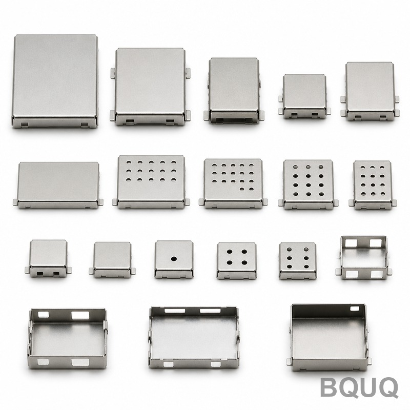
Stamped Parts for Relays and Switches: Contacts, Springs and Yokes
Short answer: a relay or switch is, mechanically, three stamped problems. The contact must carry rated current and survive switching arcs; the spring blade must deliver a defined contact force for hundreds of thousands of operations; the yoke must carry magnetic flux without sticking. In production these parts are stamped from strip just 0.1–2.0 mm thick: silver or silver-clad copper for contacts, beryllium copper, phosphor bronze or stainless spring steel for blades, and low-carbon magnetic steel for yokes. Progressive stamping holds ±0.05 mm on them at hundreds of strokes per minute, which is why relays that cost a dollar still switch reliably for years.
Understanding what is stamped, from which material, and why, is the fastest way to get a relay or switch made right the first time. This guide walks through each functional stamped part, the material logic behind it, and the tolerances and quality details a die shop must control.
What Actually Gets Stamped Inside a Relay
Take a typical electromechanical relay apart and the stamped parts list is longer than you expect. The coil wire and the bobbin are not stamped, but almost everything else is: the fixed and movable contacts, the contact spring blades, the armature, the yoke, the core frame, and the coil terminals that exit the housing. A compact automotive relay commonly contains five to eight distinct stamped parts, all produced on progressive dies from coil stock and then assembled on automated lines.
| Part | Typical material | Strip thickness | Critical requirement |
|---|---|---|---|
| Contact (fixed/movable) | AgSnO2, AgNi or Ag-clad copper | 0.2–0.6 mm | Arc erosion life, low contact resistance |
| Contact spring blade | Beryllium copper, phosphor bronze, 301 stainless | 0.10–0.30 mm | Stable force over 100k–1M cycles |
| Yoke | Low-carbon steel DC01/1008/SPCC | 0.8–1.5 mm | Magnetic softness, low residual magnetism |
| Armature | Low-carbon steel, often nickel plated | 0.8–1.5 mm | Flux attraction, corrosion resistance |
| Terminals | Brass or tin-plated copper alloy | 0.4–0.8 mm | Solderability, pull strength |
| Core frame | Low-carbon steel | 0.6–1.2 mm | Flux path, rivet/bend integrity |
The economics only work because stamping does everything at once. One progressive die can blank, form, coin, bend, and cut off a finished contact spring at several hundred strokes per minute, so per-part cost lands in fractions of a cent to a few cents depending on material and plating. That is why relay makers do not machine these parts and why, when you source stamped contacts and terminals from a dedicated die shop, the unit price is a rounding error compared with the design work.
Contacts: Carrying Current and Surviving the Arc
The contact is where a relay earns or loses its life. Every make and break draws a micro-arc that erodes material and oxidizes the surface, so contact material choice is driven by switching duty, not by conductivity alone.
| Contact material | Typical duty | Erosion/behavior | Indicative cost vs fine silver |
|---|---|---|---|
| Fine silver (Ag) | Low load, general purpose | Soft, arcs pit it | Baseline |
| AgNi 0.15–0.20 | Moderate load, motor/appliance | Resists welding, low resistance | ~1.0–1.1× |
| AgSnO2 | High inrush, ≥10 A loads | Best arc resistance, runs warmer | ~1.1–1.3× |
| AgCdO (legacy) | Historical high-load | Excellent but cadmium restricted | n/a in EU |
| Silver-clad copper strip | Cost-driven designs | Silver face does the switching | ~0.6–0.8× |
| Gold (selective) | Signal-level, low voltage | No oxide film, µA–mA rated | High, used sparingly |
Two production routes dominate. Solid silver-alloy contacts are often staked or riveted from wire, while stamped contacts come from silver-clad or inlay strip where a silver layer is roll-bonded onto a copper or brass carrier and the contact pad is stamped in place. The clad route saves material because silver only exists where the contact touches, and it suits high-volume progressive stamping. For signal relays and switches that switch microvolts, oxidation is the enemy: a silver or tin surface films over and fails at low voltage, which is why telecom-grade contacts get selective gold or gold-alloy plating. Plating thickness, porosity, and where the gold stops matter enough that we treat it as a plating design problem of its own, not an afterthought.
Springs and Blades: Force Delivered for a Million Cycles
The spring blade is the part that guarantees contact pressure. If it relaxes, contact resistance climbs, the switch runs hot, and eventually the load welds the contacts closed. So blade material selection is a fatigue-and-relaxation decision as much as a conductivity one.
| Blade material | Conductivity | Fatigue/relaxation | Relative cost | Typical use |
|---|---|---|---|---|
| Phosphor bronze C5210 | Moderate | Good, budget choice | 1.0× | General contacts, clips |
| Beryllium copper C17200 | Good | Excellent, low relaxation | 3–5× | Precision relay springs |
| 301 stainless, high yield | Poor | Good below ~150 °C | 1.5–2× | Corrosion-resistant contacts |
| Brass, hard | Moderate | Relaxes at temperature | 0.8× | Non-critical terminals only |
The engineering rules are the same ones that govern any electronic contact spring: keep working stress below roughly 50–60% of yield, let the bend radius respect the grain, and never leave the burr on the tension side of a bend where it acts as a crack starter. Contact force targets on small relays commonly run 20–150 cN; a good die shop will coin the contact area and control material hardness so the force does not drift between lots. Springback compensation is done in the die geometry and verified on a force tester, because a blade that is 0.05 mm off in form can shift contact force by 10% or more. If your design needs a separate coiled spring instead of a stamped blade, that is a custom spring question with its own material and tolerance rules.
Yokes and Armatures: Magnetic Steel That Must Not Stick
Relay yokes and armatures look like ordinary steel brackets, but they are a special case: they must be magnetically soft. Low-carbon steel such as DC01, 1008, or SPCC carries flux well, but stamping cold-works the edges and raises coercivity, which can slow release or increase residual magnetism. For sensitive designs, specify a stress-relief or full anneal after stamping to restore soft magnetic behavior, and avoid specifying spring-tempered steel entirely — a hardened yoke is a sticky relay.
Corrosion handling matters too, because rust on the magnetic surfaces changes both flux and contact gap. Typical finishes are nickel plating 3–8 µm or zinc with clear passivation; nickel is preferred where the yoke doubles as a current path. If your relay must release quickly and reliably, tell the factory: design rules such as limiting overtravel, controlling the air gap, and keeping the armature mass low are cheap on paper and expensive to retrofit into a stamped design later.
Tolerances, Burr Direction and Coplanarity
Stamped relay parts generally run ±0.05 mm on functional dimensions, with ±0.02 mm achievable on critical features using fine-blanking or precision dies. What catches buyers out is the details the drawing never shows. Burr height on a 0.3 mm blade should hold under ~0.03–0.05 mm, and burr direction must be specified — burr on the wrong side of a contact surface creates resistance drift, and burr on the tension side of a bend shortens fatigue life. Coplanarity matters on twin contacts where make-before-break sequencing is defined by height differences of a few hundredths of a millimeter. A reliable die shop controls these with in-die coining, regular hardness testing of incoming coil, and first-article reports that record burr side, plating thickness, and contact force — the same discipline we apply across our metal stamping process line.
When you RFQ, send the drawing with material grade, strip thickness, force or travel spec on springs, plating spec, and the switching load. With that, a source factory in Dongguan can quote tooling (typically $3,000–$15,000 for a progressive relay-parts die, indicative) and per-part price in one pass, and you can judge the quote on facts instead of assumptions.
Frequently Asked Questions
Q: Can contacts be stamped directly, or do they have to be riveted?
A: Both routes are production-standard. Solid silver-alloy contacts are often upset from wire and staked into the blade, while silver-clad or inlay strip lets a progressive die stamp the contact pad in one pass. Clad stamping wins at high volume because silver is used only where switching happens and the assembly step disappears.
Q: What steel should a relay yoke use, and can it be stainless?
A: Use low-carbon magnetic steel such as DC01, 1008, or SPCC — magnetically soft, cheap, and stampable. Standard stainless is not magnetically soft enough for efficient relay flux paths, and hardened or spring-tempered steel increases residual magnetism and slow release.
Q: Why does my stamped spring lose force after a few thousand operations?
A: Either working stress is too close to yield, the material relaxes at your operating temperature, or the burr sits on the tension side of the bend and cracks early. Check stress levels against yield, verify strip hardness, and specify burr side on the drawing. Beryllium copper and 301 stainless hold force far better than hard brass.
Q: What plating is right for relay and switch contacts?
A: It depends on load. Power contacts usually run bare silver alloy or silver-clad material where the alloy itself resists arcing. Signal contacts that switch microvolts need gold or gold-alloy plating to avoid oxide film failure. Specify thickness, porosity limits, and where plating must stop if you need selective plating.
Q: What tolerances can you actually hold on stamped relay parts?
A: Production stamping holds ±0.05 mm on functional dimensions as standard, with ±0.02 mm on critical features using precision or fine-blanking dies. Burr height, coplanarity, and contact force are controlled and reported per batch rather than assumed.
Related Resources
- Stamped Contact Plating: Gold, Silver and Tin Strategies — how plating choice and thickness decide switching reliability.
- Electronic Contact Springs: Materials and Force Design — blade and spring design rules for contacts that must last.
- About BQUQ — an ISO9001-certified source factory in Dongguan running stamping, springs, CNC and heat sinks under one roof.
- Contact us — send your relay or switch drawing and get a quotation within 12 working hours.
Authored by the BQUQ Engineering Team. BQUQ is an ISO9001-certified source factory in Dongguan, China, running CNC machining, metal stamping, custom springs, heat sink and collet lines under one roof. Send drawings to sc@bquq.com or WhatsApp +86 13713157787 for a quote within 12 working hours. www.bquq.com


