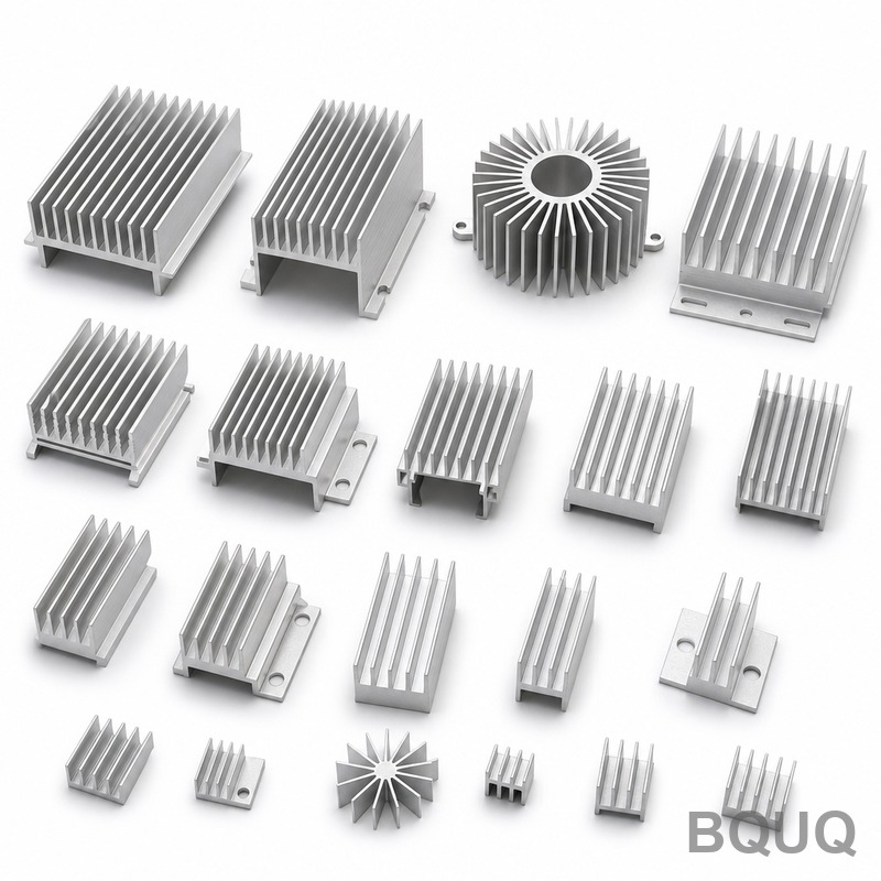
1U Server Stamped Fin Heatsink Assembly: 0.3mm Fins, 0.05mm Base, 10K-50K/mo
In a 1U AI server, every millimeter of height is contested and every watt of heat has only a thin, fast stream of forced air to escape through. A stamped-fin heatsink assembly answers this with maximum fin surface in minimum space - but only if the fins stay true at 0.3mm thickness, the base stays flat at 0.05mm, and the fin-to-base joint survives shock, vibration and thousands of thermal cycles. Holding all of that at 10,000 to 50,000 pieces a month is a manufacturing discipline problem as much as a design one.
Project Background & Challenge
Our client is a North American ODM building AI training and inference servers for hyperscale data center customers. Their latest 1U platform cools memory VRMs and ASIC power stages with compact air-cooled heatsinks seated over the components through a thermal interface: a fin pack roughly the size of a playing card, barely 20mm tall, sitting directly in the exhaust path of high-static-pressure fans.
The drawing specified 6063 aluminum throughout: fins stamped from 0.3mm sheet at a tight, uniform pitch to pack the most surface area into the allowed height, and a solid machined base whose contact face must be flat to 0.05mm so the thermal interface layer stays at its designed thickness everywhere on the die. The assembly method was fixed as swaged/press-fit fin construction - fins with interlocking features pressed into slots machined into the base, forming a mechanical joint with low interface resistance rather than relying on thermal epoxy alone.
The previous build had struggled on three fronts. Stamped 0.3mm fins are fragile; handling and packing caused bent fins and rejections. Epoxy-bonded fin joints from the earlier supplier degraded in thermal cycling, and interface resistance crept up until units failed field thermal margin tests. And the volumes - jumping from 10,000 toward 50,000 pieces a month as the AI platform ramped - exceeded the incumbent's stamping and assembly capacity. The client needed one factory that could stamp the fins, machine the bases, assemble and verify the joints, and ship monthly without the yield collapsing.
BQUQ Process Solution
BQUQ ran the part as a single flow - stamping, CNC machining and fin assembly under one roof - so fin geometry, base flatness and joint integrity were controlled by one quality system instead of three suppliers.
Stamped Fin Manufacturing
Fins are blanked and formed in progressive stamping dies from 0.3mm 6063 aluminum sheet. The die design integrates the interlocking foot feature into the same stroke as the blanking, so fin height, pitch and foot geometry stay consistent across millions of hits; die wear is checked against a fixed maintenance calendar rather than waiting for out-of-tolerance parts. Deburring is part of the die sequence, because a 0.3mm fin with a burr is both a handling hazard and an airflow noise source in a 1U chassis. Fins are formed and transferred in dedicated trays from the press onward, so the fins are never touched loose - this single change took fin-handling rejects out of the yield equation.
CNC Machining of the Base
Bases are machined from 6063 aluminum plate with the fin slots milled to match the stamped fin feet, and the component contact face finished flat to 0.05mm, verified by CMM sampling on first articles and at a fixed in-process cadence. Slot width and position are machined in the same setup as the contact face, so the fins stand square and the joint line-up never depends on a second clamping. Slot-to-slot spacing is held to the fin pitch, which keeps the airflow channels between fins uniform - critical for predictable pressure drop across the fin pack at 1U fan curves.
Swaged Fin Assembly and Joint Verification
Assembly is a controlled press-fit operation: fins are inserted into the machined slots and swaged so the base material locks the fin feet mechanically. The mechanical joint carries the structural load, so thermal interface at the fin root stays thin and stable through thermal cycling instead of depending on an adhesive layer that pumps out over life. Joint integrity is verified by sample pull testing on fins from each production lot, plus periodic section checks of the swaged interface. Assemblies are then black anodized, which both matches the chassis aesthetic and raises surface emissivity for better radiation-assisted dissipation inside the 1U airflow.
Fin geometry is where stamped assembly earns its keep: fins are blanked at 0.3 mm thickness and checked for pitch and height on a profile projector, holding pitch within ±0.1 mm so airflow between fins stays uniform across the width of the sink. Fins are pressed into the base plate grooves and mechanically bonded, then the assembly is machined on the mounting face to 0.05 mm flatness before black anodizing, with masking applied where the power module contacts the base.
Key Specifications
| Item | Specification |
|---|---|
| Material | 6063 aluminum (stamped fins + machined base) |
| Fin thickness | 0.3mm stamped fins, progressive die |
| Fin pitch | Uniform pitch per drawing, machined-slot matched |
| Base flatness | 0.05mm on component contact face |
| Assembly | Swaged / press-fit fin-to-base, mechanical joint |
| Surface finish | Black anodized |
| Volume | 10,000-50,000 pcs/month |
| Inspection | CMM flatness, fin pull test per lot, section checks, CPK≥1.33 on critical dimensions |
| Delivery | Samples in 3-7 days, first batch in 12-20 days |
Quality Control & Delivery
The part runs under an ISO9001:2015 quality system. First-article inspection covers full CMM layout of the base, contact-face flatness, slot positions and fin-pack squareness; each production lot is sampled for fin pull strength, and swaged interfaces are section-checked on a fixed schedule. In-process data tracks stamping dimensional drift and base flatness, with CPK held at ≥1.33 on critical dimensions. Because stamping, machining and assembly happen in one factory, a drift in fin geometry is caught at the base-machining stage instead of arriving as a non-fit at final assembly.
Result: samples approved within 7 days, the first production batch delivered inside the agreed window, and monthly volume scaled from 10,000 toward 50,000 pieces without a yield cliff. Field thermal margin failures tied to fin-joint degradation dropped to zero over the following two quarters, and incoming inspection at the client simplified to flatness and pull-test verification against BQUQ's lot data.
Related Products & Resources
For other fin-assembly constructions and scale examples, see:
- Custom Swaged Fin Heatsink
- Custom Extruded Aluminum Heatsink Collection
- Robot Joint Module: Four Processes, One Factory - how BQUQ combines processes under one quality system
FAQ
How thin can stamped fins go, and why 0.3mm here?
Stamped fins can start from 0.3mm - below extrusion limits - which is exactly why high-density 1U fin packs use this process. At 0.3mm with tight pitch, the fin pack gains surface area in the allowed height, while the stamped construction keeps the fins light enough not to load the swaged joint.
How is the 0.05mm base flatness maintained at high volume?
The contact face is finished by CNC in the same setup as the fin slots, then CMM-sampled at a fixed in-process frequency with CPK≥1.33 tracked on rolling batches. Flatness data ships with each lot, so flatness control does not depend on end-of-line sorting.
Is a swaged fin joint strong enough compared with epoxy bonding?
The swaged joint locks each fin mechanically into the machined base, and every production lot is verified by fin pull testing plus periodic section checks. Because there is no adhesive layer to pump out or degrade, interface resistance stays stable through thermal cycling - which is what fixed the field failures in this case.
What are the lead times and volume limits?
Samples take 3-7 days and a first batch ships in 12-20 days. Stamped-fin heatsink assemblies run from 1K to 100K pieces a month; this project ramped from 10,000 to 50,000 pieces a month on rolling schedules without re-qualification.