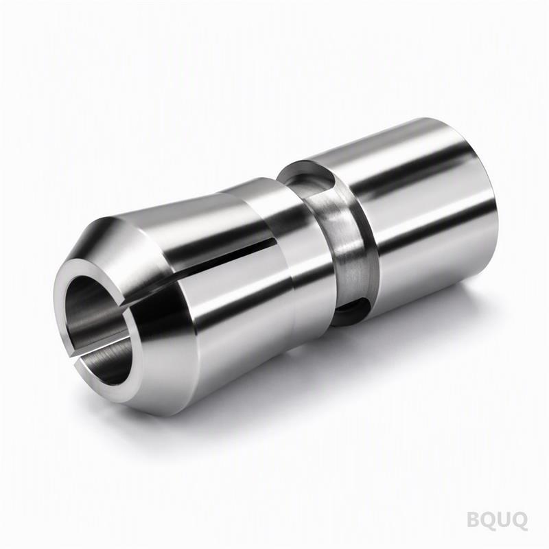
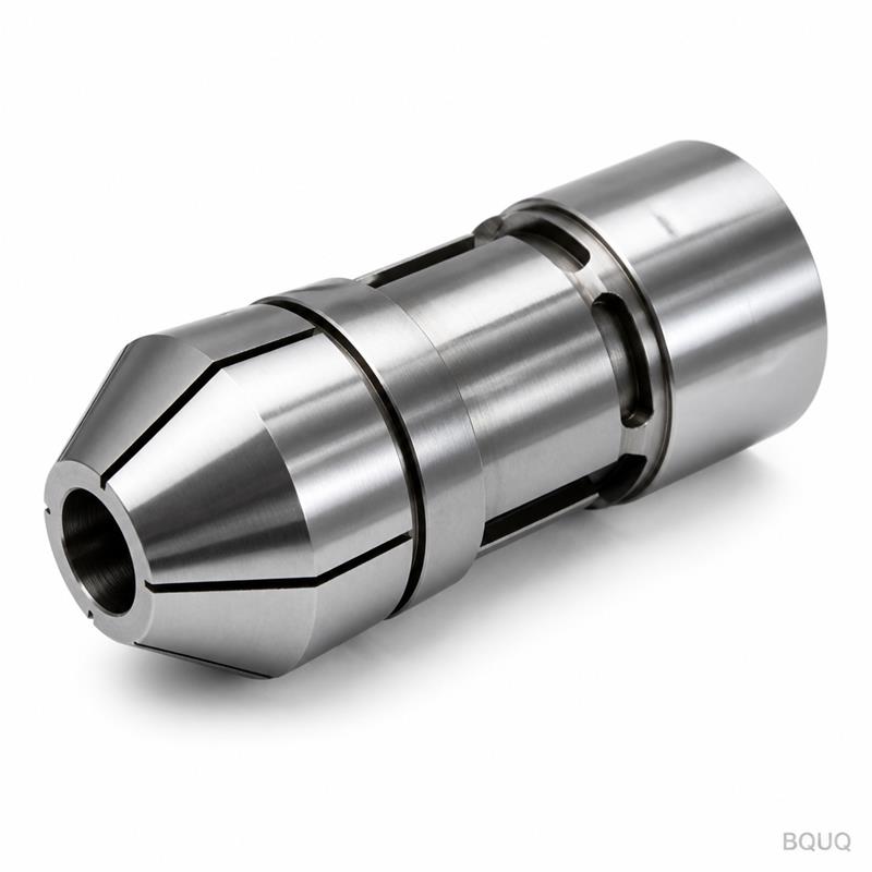
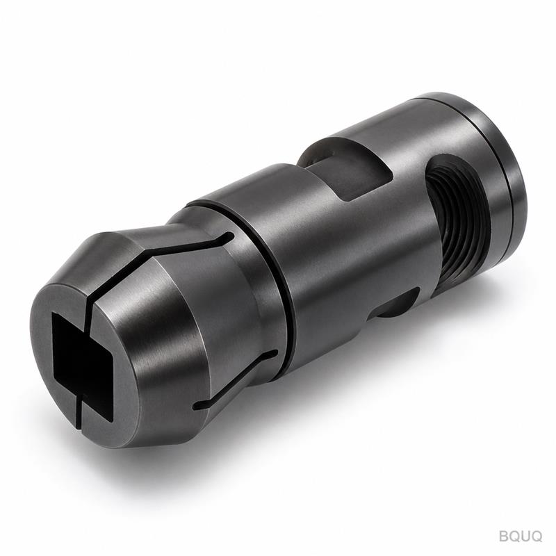
This is a CNC machined Auto Lathe 650 Type Round Bore Spring Collet Chuck, built for automatic lathe spindles that demand tight concentricity and repeatable gripping force. You ge
BQUQ CNC Machined Auto Lathe 650 Type Round Bore Spring Collet Chuck
This is a CNC machined Auto Lathe 650 Type Round Bore Spring Collet Chuck, built for automatic lathe spindles that demand tight concentricity and repeatable gripping force. You get a guaranteed runou
Get a Fast Quote for This Part
Send us your drawing / quantity / material — reply within 24h.
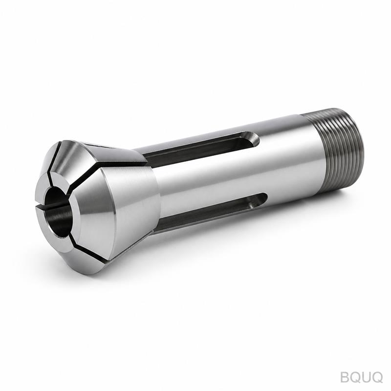
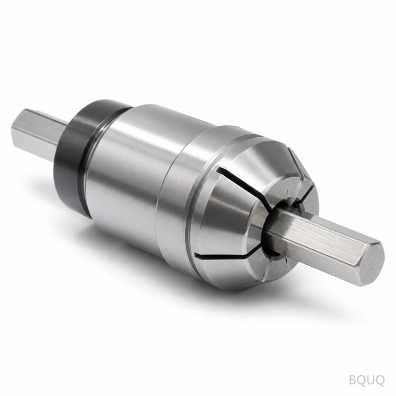
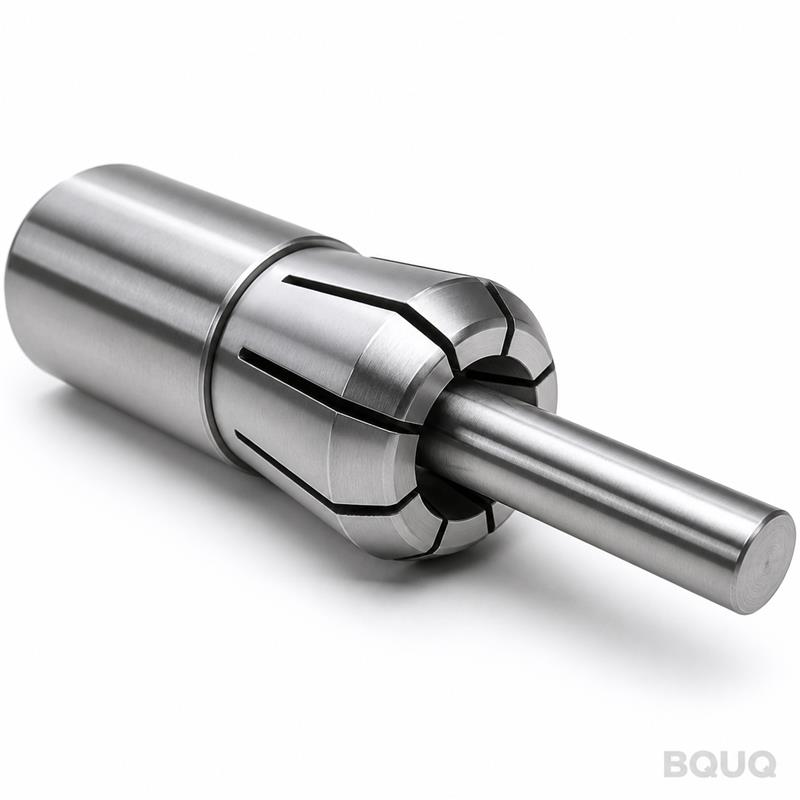
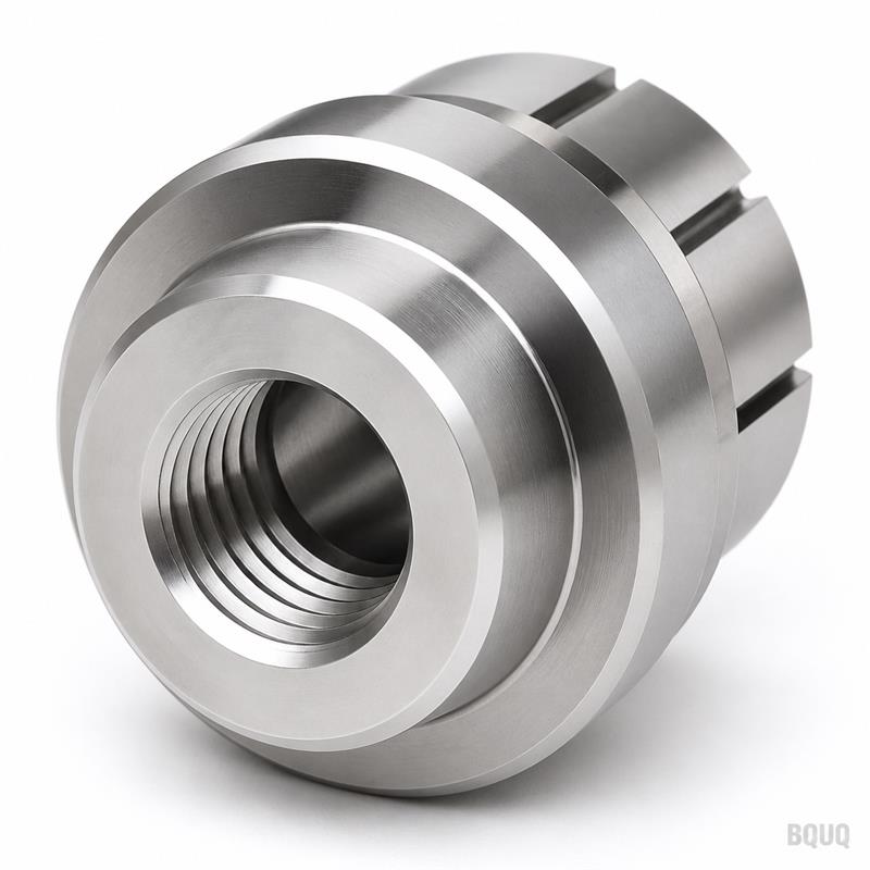
This is a CNC machined Auto Lathe 650 Type Round Bore Spring Collet Chuck, built for automatic lathe spindles that demand tight concentricity and repeatable gripping force. You get a guaranteed runout of 0.005 mm TIR, a hardened body at 58–60 HRC, and a lead time of 7 business days for standard sizes. It is a direct replacement for worn or low-grade collet chucks, machined from solid bar stock in our Dongguan factory.
How the 650 Type Round Bore Achieves 0.005 mm TIR
The 650 Type refers to the front-end taper geometry and thread pitch used on specific auto lathe spindles (common on Citizen, Star, and Tsugami sliding head machines). The round bore is ground after CNC turning, not just turned, to remove thermal distortion and tool marks. We hold the internal bore diameter to a +0.005 / -0.000 mm tolerance, which allows the spring collet to collapse evenly around the workpiece. The chuck body is machined in one clamping operation on a 5-axis CNC mill-turn center, eliminating re-fixturing errors. This is why we can state 0.005 mm TIR at the nose, verified on a Talyrond 365 roundness tester before packing.
Material Selection: Why We Use 8620 Alloy Steel Over 12L14
Many cheap collet chucks are made from 12L14 free-cutting steel because it is fast to machine. We do not use it. The 650 Type requires wear resistance and dimensional stability under repeated clamping cycles. We machine the body from AISI 8620 carburizing alloy steel. After CNC machining, we carburize the bore and thread surfaces to a case depth of 0.3–0.5 mm, then harden to 58–60 HRC. The core remains tough at 35–40 HRC, which prevents cracking under side loads. The spring slot (the relief cut that allows the collet to flex) is wire-cut after heat treatment, not milled before, so the slot edges stay sharp and stress-free. If you are comparing materials, 8620 gives you 3x the wear life of 12L14 in this application.
Grinding Sequence That Eliminates Bore Distortion
Heat treatment always moves steel. To counter this, we leave 0.15 mm stock on the bore and 0.10 mm on the taper after hardening. The final grinding sequence is: (1) grind the front taper to a master gauge, (2) grind the round bore to size using a CBN wheel, (3) re-grind the taper again to correct any induced distortion. This two-step taper grind is the difference between a chuck that holds 0.015 mm and one that holds 0.005 mm. We also grind the back face flat to 0.002 mm to ensure proper seating against the spindle face. Surface finish on the bore is Ra 0.4 µm, which reduces workpiece scoring and allows higher clamping torque without marking soft materials like brass or aluminum.
Inspection Before Every Shipment: Air Gauge and Hardness Test
Every single chuck, not a sample batch, goes through three checks. First, we measure the round bore diameter with a digital air gauge (resolution 0.0005 mm) to confirm the +0.005/-0.000 tolerance. Second, we mount the chuck on a test mandrel and measure TIR at the nose with a 0.001 mm dial indicator; reject if over 0.005 mm. Third, we test hardness on the bore surface with a Rockwell tester; reject if below 58 HRC. We also check thread fit with a GO/NO-GO plug gauge. You receive a signed inspection report with each shipment, including the actual measured values and a photo of the TIR reading.
Specifications for the CNC Machined Auto Lathe 650 Type Round Bore Spring Collet Chuck
Parameter
Value / Range
Product Type
Round Bore Spring Collet Chuck (Auto Lathe 650 Type)
Material (Body)
AISI 8620 Alloy Steel (carburized)
Hardness (Case)
58–60 HRC
Hardness (Core)
35–40 HRC
Case Depth
0.3–0.5 mm
Round Bore Tolerance
+0.005 / -0.000 mm
Runout (TIR at Nose)
0.005 mm max
Surface Finish (Bore)
Ra 0.4 µm
Back Face Flatness
0.002 mm
Available Bore Sizes
Ø3 mm to Ø42 mm (in 0.5 mm increments)
Lead Time (Standard)
7 business days
MOQ
No MOQ (single piece accepted)
Country of Origin
Made in China (Dongguan)
Why This Chuck Works for Swiss-Type and Sliding Head Lathes
The 650 Type is most commonly used on Swiss-type automatic lathes where the guide bushing and collet chuck work together to support long, slender workpieces. Because the round bore collapses evenly, you can feed bar stock continuously without scoring. For sliding head machines, the chuck’s short overall length (typically 35 mm) reduces interference with the guide bushing. If you run brass, copper, or 6061 aluminum, the Ra 0.4 µm bore finish prevents galling. For steel workpieces, the 8620 hardened bore resists wear from abrasive scale. This chuck is also a direct replacement for older 650 Type chucks from Japanese machine builders—our thread pitch and taper angle match the original JIS standard.
Customizing the Bore Size and Slot Geometry
If your workpiece diameter is not in the standard 0.5 mm increment chart, we can machine the bore to any size between Ø3 mm and Ø42 mm within 48 hours. The spring slot width can also be adjusted (standard is 1.0 mm) to change the gripping force range. For thin-wall tubing, we can cut a wider slot (up to 1.6 mm) to reduce collapse force and prevent crushing. For hardened steel bars, we can reduce the slot width to 0.6 mm for higher gripping rigidity. There is no extra charge for custom bore sizes, only for non-standard slot widths. Send us your drawing or your target workpiece OD, and we will confirm the custom geometry within one working day. Our precision manufacturing process allows us to hold the same 0.005 mm runout on custom sizes as on standard.
Frequently Asked Questions
What is the minimum order quantity for this collet chuck?
There is no MOQ—we accept a single-piece order for prototypes or replacement needs.
Can you machine the bore to my exact workpiece diameter?
Yes, we can machine the round bore to any size from Ø3 mm to Ø42 mm with the same +0.005/-0.000 tolerance, typically within 48 hours of order confirmation.
How do you verify the 0.005 mm runout before shipment?
We mount each chuck on a precision test mandrel and measure TIR at the nose with a 0.001 mm dial indicator, and we include the signed inspection report in the shipment.
What is your standard production lead time?
Standard sizes ship in 7 business days; custom bore sizes ship in 10 business days from Dongguan, China.
Related Engineering Guides for Your Selection Process
Before you finalize your chuck spec, check our CNC cutting tool selection guide for guidance on toolholder compatibility and gripping force calculations. For understanding how the 0.005 mm runout fits into your overall part tolerance stack-up, read our CNC machining tolerances guide.
Get a Firm Quote Within 12 Hours
Send us your drawing, target bore size, and quantity. We will reply with a firm price, lead time, and a DFM comment if we see a way to improve the design. No MOQ, no obligation. Email sc@bquq.com or WhatsApp +86 13713157787. We answer within 12 hours, every day.