
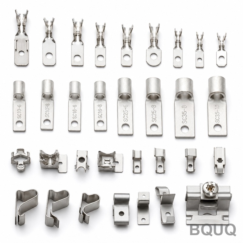
Design for Stamping: Best Practices and Common Mistakes for Precision Metal Parts
Design for Manufacturing (DFM) is the most critical phase in metal stamping. A design that neglects the physical constraints of a high-speed stamping die will result in increased unit costs, extended lead times, and compromised structural integrity. Conversely, a design aligned with stamping principles yields tolerances as tight as ±0.05 mm at production rates exceeding 500 parts per minute. This article provides a definitive engineering guide to optimizing your sheet metal parts for progressive die stamping, addressing the specific material properties, tooling limitations, and cost drivers that determine success.
## Material Selection and Bend Radius Limits The choice of material is the first determinant of stamping feasibility. Not all steels, aluminums, or coppers behave identically under shear stress and plastic deformation. For instance, standard mild steel (SPCC) offers excellent formability with a minimum bend radius of 0.5 times the material thickness (T). However, high-carbon spring steel (SK5) or stainless steel (SUS301) requires a larger bend radius, typically 1.0T to 1.5T, to prevent cracking along the outer fiber of the bend. Using a radius smaller than the material’s minimum causes stress concentrations that lead to micro-fractures, which are invisible until the part is subjected to fatigue loading.
The table below outlines baseline tolerances and bend parameters for common stamping materials.
| Material Grade | Thickness Range (mm) | Min Bend Radius | Standard Tolerance (mm) | Relative Cost Index |
| SPCC (Cold Rolled Steel) | 0.3 - 3.2 | 0.5T | ±0.10 | 1.0 |
| SUS304 (Stainless) | 0.3 - 2.0 | 1.0T | ±0.15 | 1.8 |
| AL5052 (Aluminum) | 0.5 - 3.0 | 0.8T | ±0.15 | 1.5 |
| C2680 (Brass) | 0.3 - 2.0 | 0.5T | ±0.08 | 2.2 |
| SK5 (Spring Steel) | 0.2 - 1.5 | 1.5T | ±0.05 | 2.5 |
## Critical Design Rules for Bend Relief and Corner Radii One of the most frequent mistakes in stamping design is creating flanges that intersect with adjacent walls without sufficient bend relief. When a bend line runs into a vertical wall, the material is stretched beyond its elongation limit, causing the wall to tear or distort. To prevent this, engineers must specify a relief notch at the end of the bend line. The width of this relief should be at least 1.5 times the material thickness (1.5T), and the depth must extend beyond the bend tangent line. A common rule is to set the relief depth to the inside bend radius plus the material thickness (R + T). Without this, the die will shear the material unpredictably, leaving burrs and ragged edges that require costly secondary deburring operations.
Additionally, internal corner radii must be considered. A sharp 90-degree internal corner in the flat pattern creates a stress point where the punch enters the material. The minimum recommended internal corner radius is 0.5T, but for high-volume production exceeding 100,000 parts, a radius of 1.0T is advised to extend punch life and prevent chipping. For example, a 1.0 mm thick part with a 0.3 mm internal radius will accelerate tool wear by approximately 30% compared to a 1.0 mm radius, increasing maintenance downtime and per-part cost.
## Hole Sizing, Positioning, and Web Thickness Punching holes is a shearing operation, not a drilling operation. The minimum hole diameter that can be reliably punched is generally equal to the material thickness for standard steel, but for hardened materials, it must be at least 1.2T. More critical is the distance from the hole edge to the part edge, known as the web thickness. If this distance is too small, the material between the hole and the edge will bulge or deform. The absolute minimum web thickness is 1.5T, but the recommended value for tight tolerances is 2T. For instance, a part with a 2.0 mm thickness requires a minimum distance of 4.0 mm from the edge of a hole to the edge of the part to maintain a flatness within 0.1 mm.
The table below compares the impact of hole proximity on tooling cost and secondary operations.
| Design Feature | Rule of Thumb | Impact on Tooling | Secondary Cost |
| Hole Diameter | >= 1.0T | Standard Punch | None |
| Hole Diameter | < 1.0T | High-Speed Punch / EDM | +15% Tool Cost |
| Web Thickness | >= 2.0T | Standard Die | None |
| Web Thickness | < 1.5T | Requires Die Insert | +20% Tool Cost |
| Hole to Bend Distance | >= 3.0T + R | Standard Die | None |
| Hole to Bend Distance | < 2.0T | Pre-punch required | +10% Part Cost |
## Tolerance Stack-Up and Springback Compensation Achieving tight dimensional tolerances in stamping is a battle against elastic recovery, commonly known as springback. When a sheet metal part is bent, the material’s internal stress causes it to partially return to its original shape after the punch retracts. For high-strength steels (tensile strength > 590 MPa), springback can be as high as 5 to 8 degrees on a 90-degree bend. To compensate, the die must be designed with an over-bend angle. For example, to achieve a final 90-degree angle in SUS301, the die cavity is machined to 84 degrees. This compensation is not linear across the part; it depends on the bend length, material thickness, and grain direction.
Precision tolerances also depend on the distance between features. A hole-to-hole tolerance of ±0.05 mm is achievable if the distance is under 50 mm. However, if the distance exceeds 100 mm, thermal expansion and material thickness variation introduce error, widening the achievable tolerance to ±0.15 mm. For critical alignment features, designers should specify datum targets on the same side of the strip to minimize cumulative error from the feeding mechanism. The stamping press feed accuracy at BQUQ is ±0.03 mm, but this does not eliminate the need for robust design tolerances.
## Cost Drivers: Tooling Complexity vs. Unit Price The decision to combine operations into a single progressive die versus using multiple simple dies is a primary cost driver. A progressive die that performs blanking, forming, and coining in one stroke has a higher initial tooling cost but drastically reduces unit price for high volumes. For a medium-complexity part (10mm x 20mm), a standard progressive die costs between $3,000 and $8,000 USD with a 4-week lead time. A transfer die with cam slides for complex bending can cost $15,000 to $30,000 USD with a 10-week lead time.
The break-even point for tooling complexity is typically around 50,000 units. If your annual volume is below this threshold, a simpler die with multiple stages is more economical. However, for volumes exceeding 200,000 units, the higher tooling cost is amortized quickly, and the reduced per-part cycle time (from 3 seconds to 0.5 seconds) provides significant savings. Additionally, consider that adding a tapping operation in the die increases tooling cost by 15% but eliminates a separate machine setup, reducing overall lead time by 5 days.
## FAQ-Style Design Checks and Practical Tips Engineers often ask about the viability of sharp external corners. The answer is to avoid them; specify a chamfer or radius of at least 0.3 mm to prevent burr formation and die chipping. Regarding burr direction, always specify the burr side on the drawing; the burr will occur on the lower side of the punch, and this must be oriented away from sliding surfaces. For threaded holes, do not rely on stamping to form threads; instead, design for self-clinching nuts (PEM) which require a specific hole size, typically a tolerance of +0.08/-0.00 mm.
Another common mistake is specifying a surface finish that requires post-stamping grinding. Stamping produces a sheared edge with a burnish zone of about one-third the material thickness. If you require a smooth edge, you must specify a shaving operation, which adds 0.5 seconds to the cycle time and increases tool cost by 8%. If the part requires a flatness of 0.1 mm across a 100 mm length, a coining operation is required after bending. Coining applies high pressure (up to 200 tons per square inch) to flatten the material, but this also work-hardens the surface, which may affect subsequent welding.
## Conclusion and Engineering Recommendation Optimal stamping design is a balance between geometric simplicity and functional necessity. By adhering to the material-specific bend radii, providing adequate bend relief, and respecting minimum web thicknesses, you can achieve tolerances of ±0.05 mm without inflating tooling costs. We recommend submitting your 3D model for a DFM analysis before finalizing the tooling design. At BQUQ, our engineers review every part for springback compensation and die clearance (typically 5% to 10% of material thickness per side) to ensure first-pass qualification.
For a professional evaluation of your stamping design, contact our engineering team for a 12-hour quoting service. We provide immediate feedback on manufacturability and cost reduction opportunities.
Email: sc@bquq.com WhatsApp: +86 13713157787 www.bquq.com


