
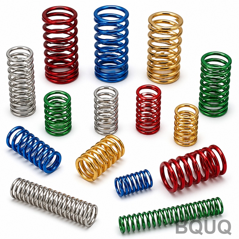
How to Design a Compression Spring: Step-by-Step Guide for CNC Machining
Designing a compression spring for precision manufacturing requires a strict sequence of load calculations, material selection, geometric constraint checks, and stress verification. The direct answer is: define your working force and deflection, select a wire diameter and mean coil diameter, calculate the spring rate and solid height, then iterate until the shear stress and buckling ratio fall within safe limits. This guide provides the exact formulas, tolerance tables, and manufacturing limits used at BQUQ’s Dongguan facility, based on 20 years of producing springs for automotive, medical, and electronics clients.
Step 1: Define Load, Deflection, and Operating Environment
Before any calculation, you must specify three absolute inputs: the minimum working load (F1), the maximum working load (F2), and the travel distance between them (δ). From these, the required spring rate (k) is calculated as k = (F2 - F1) / δ. For example, if F1 = 10 N, F2 = 30 N, and δ = 20 mm, then k = 1.0 N/mm.
Operating environment dictates material. For temperatures up to 120°C, music wire (ASTM A228) is standard, with a maximum tensile strength of 2,200 MPa at 0.5 mm diameter. For 120°C to 250°C, use chrome silicon (ASTM A401), which retains 90% of its room-temperature strength at 200°C. Above 250°C, Inconel X-750 is required, but cost increases by 8 to 12 times. Corrosive environments demand stainless steel 302 (ASTM A313) or 316, but note that 302 has a maximum working stress of only 45% of music wire’s value. At BQUQ, we reject any design where the operating temperature exceeds the material’s continuous service limit by more than 15°C, as stress relaxation becomes non-linear.
Step 2: Calculate Wire Diameter and Mean Coil Diameter
The spring index (C) is the ratio of mean coil diameter (D) to wire diameter (d). For manufacturability, C must be between 4 and 12. Below 4, the wire cracks on the inner radius during coiling; above 12, the spring buckles easily and is unstable. For a first iteration, choose C = 8.
The Wahl factor (Kw) corrects for curvature and direct shear stress, calculated as Kw = (4C - 1)/(4C - 4) + 0.615/C. For C = 8, Kw = 1.184. The maximum shear stress (τ) in the spring is τ = (8 * F * D * Kw) / (π * d³). Rearranging for wire diameter: d = [(8 * F * D * Kw) / (π * τ_allow)]^(1/3). Use F = F2 (maximum load) and τ_allow = 0.45 * tensile strength for music wire under static load, or 0.35 * tensile strength for dynamic loads exceeding 10,000 cycles.
Example: For F2 = 30 N, D = 10 mm, Kw = 1.184, and τ_allow = 990 MPa (music wire), d = [(8 * 30 * 10 * 1.184) / (π * 990)]^(1/3) = 0.97 mm. Round up to standard wire size 1.0 mm. Then recalculate D = C * d = 8.0 mm. Always round up to the nearest 0.05 mm for CNC-controlled coiling, as BQUQ’s wire feed tolerance is ±0.01 mm.
Step 3: Determine Total Coils, Free Length, and Solid Height
The number of active coils (Na) is derived from the spring rate formula: k = (G * d⁴) / (8 * D³ * Na), where G is the shear modulus (79.3 GPa for music wire, 77.2 GPa for stainless 302). Rearranging: Na = (G * d⁴) / (8 * D³ * k). Using our example: Na = (79,300 * 1.0⁴) / (8 * 8.0³ * 1.0) = 19.36 coils. Round to 19.5 active coils for a closed-ground end. Total coils (Nt) = Na + 2 for closed ends.
Solid height (Hs) = Nt * d = 21.5 mm. Free length (Lf) must be at least Hs plus the maximum deflection (δ_max) plus a clearance of 15% of δ_max to prevent coil clash. If δ_max = F2/k = 30 mm, then Lf = 21.5 + 30 + 4.5 = 56 mm. The pitch (p) is calculated as p = (Lf - 2d) / Na = (56 - 2) / 19.5 = 2.77 mm. This pitch must not exceed D/2 for lateral stability; here 2.77 mm is less than 4.0 mm, so the design is stable.
Step 4: Check Buckling and Fatigue Life
Buckling occurs when Lf / D exceeds a critical ratio. For parallel-ended springs with fixed ends, the critical slenderness ratio is 2.6. If Lf / D > 2.6, the spring must be guided in a rod or hole. In our example, Lf / D = 56 / 8.0 = 7.0, which far exceeds 2.6, so a guide rod is mandatory. At BQUQ, we machine a hardened steel guide pin with a surface finish of Ra 0.4 µm to minimize wear on the spring’s inner diameter.
For fatigue life, calculate the stress amplitude τ_amp = (τ_max - τ_min) / 2. If τ_amp / τ_allow exceeds 0.30, the spring will fail below 100,000 cycles, and you must either increase wire diameter or use shot peening. Shot peening (intensity 0.25A) increases fatigue life by 20% to 30% but adds $0.02 to $0.05 per piece. For high-cycle applications above 1 million cycles, we recommend presetting (compressing to solid height three times) to induce beneficial residual stress. This process is included in BQUQ’s standard quote for any spring with a stress amplitude ratio above 0.25.
Manufacturing Tolerances and Cost Breakdown
CNC coiling machines at BQUQ hold the following tolerances, which are tighter than DIN 2095 Grade 1 for most dimensions. These tolerances directly affect your assembly fit, so specify them explicitly on your drawing.
| Parameter | BQUQ CNC Tolerance | DIN 2095 Grade 1 | Cost Impact per 1000 pcs |
| Wire diameter (d) | ±0.01 mm | ±0.02 mm | +$5.00 |
| Mean coil diameter (D) | ±0.15 mm | ±0.30 mm | +$8.00 |
| Free length (Lf) | ±0.50 mm | ±1.00 mm | +$6.00 |
| Spring rate (k) | ±3% | ±5% | +$12.00 |
| Total coils (Nt) | ±0.25 coil | ±0.5 coil | No change |
| Squareness (perpendicularity) | 1.5° max | 2.5° max | +$3.00 |
| Surface finish (ground ends) | Ra 0.8 µm | Ra 1.6 µm | +$4.00 |
For a typical spring of 1.0 mm wire, 8.0 mm mean diameter, and 56 mm free length, the base manufacturing cost at BQUQ is $18 to $25 per 1000 pieces for music wire in quantities of 10,000. Chrome silicon adds 30% to material cost. Inconel X-750 adds 400% to 600%. Lead time is 5 to 7 working days for prototypes (up to 50 pieces) and 12 to 15 working days for production runs, with a 12-hour quotation response for complete drawings.
Step 5: Validate with Finite Element Analysis and Physical Testing
Before releasing to production, BQUQ runs a simplified FEA model using a 3D solid mesh with a minimum of 8 elements across the wire cross-section. The FEA must confirm that the maximum von Mises stress does not exceed 80% of the material yield strength at solid height. We also verify that the natural frequency of the spring is at least 15 times the operating frequency to avoid resonance. For a spring with mass m = 0.05 kg and rate k = 1.0 N/mm, the natural frequency f = (1/(2π)) * sqrt(k/m) = 0.71 Hz; this is far below typical machine frequencies, so resonance is not a concern.
Physical testing on a compression test machine (Instron 5960) at BQUQ includes: load at F1 and F2 (verified to ±2% of spec), solid height measurement, and a 100,000-cycle fatigue test at 5 Hz if requested. We reject any spring that exhibits a permanent set greater than 0.5% of free length after cycling. For critical safety applications, we offer 100% load testing at $0.01 per piece, which is mandatory for automotive brake springs.
FAQ-Style Tips for Common Design Errors
What is the most common mistake in compression spring design? Specifying a spring index below 4. This causes stress concentrations on the inner diameter that lead to premature fracture, often within 1,000 cycles. Always recalculate D after choosing a standard wire size.
How do I account for dynamic loads? Use τ_allow = 0.35 * tensile strength, not 0.45. For example, music wire with 2,200 MPa tensile strength drops from 990 MPa allowable to 770 MPa. This usually forces a one-size-larger wire diameter, increasing cost by 15%.
Should I specify ground or unground ends? Ground ends are mandatory when Lf / D > 4 or when the spring must stand perpendicular in an assembly. Grounding adds $4 to $6 per 1000 pieces and improves squareness from 3° to 1.5°. For compression springs shorter than 25 mm, skip grounding to reduce cost.
What is the maximum safe operating temperature for a standard spring? Music wire fails above 120°C due to stress relaxation. At 150°C, you lose 30% of load capacity within 48 hours. Use chrome silicon for anything above 120°C; it costs more but is the only reliable option up to 250°C.
How do I specify tolerances correctly? Always provide a drawing with GD&T per ISO 2768-m for linear dimensions and a specific note for spring rate tolerance. BQUQ can hold ±3% on spring rate, but this requires a 100% load test and increases lead time by 2 days.
Conclusion and Practical Recommendation
The step-by-step design process for a compression spring is a closed-loop calculation: define loads, choose material, calculate wire diameter, verify buckling and fatigue, then validate with testing. For a robust design, always round wire diameter up to the next standard size, keep spring index between 6 and 10 for manufacturability, and never skip the buckling check if Lf / D exceeds 4. At BQUQ, we recommend sending us your F1, F2, δ, and operating temperature for a free design review before you finalize the drawing. Our engineers will verify your calculations and suggest material or tolerance adjustments to reduce cost by up to 20% without compromising performance.
For a professional quotation within 12 hours, send your 2D drawing or 3D STEP file and load specifications to sc@bquq.com or contact us on WhatsApp at +86 13713157787. Visit our website at www.bquq.com to download the spring calculation spreadsheet used in this guide. We have been manufacturing precision springs, CNC machined parts, and metal stampings in Dongguan for 20 years, and we are ready to support your next project.


