
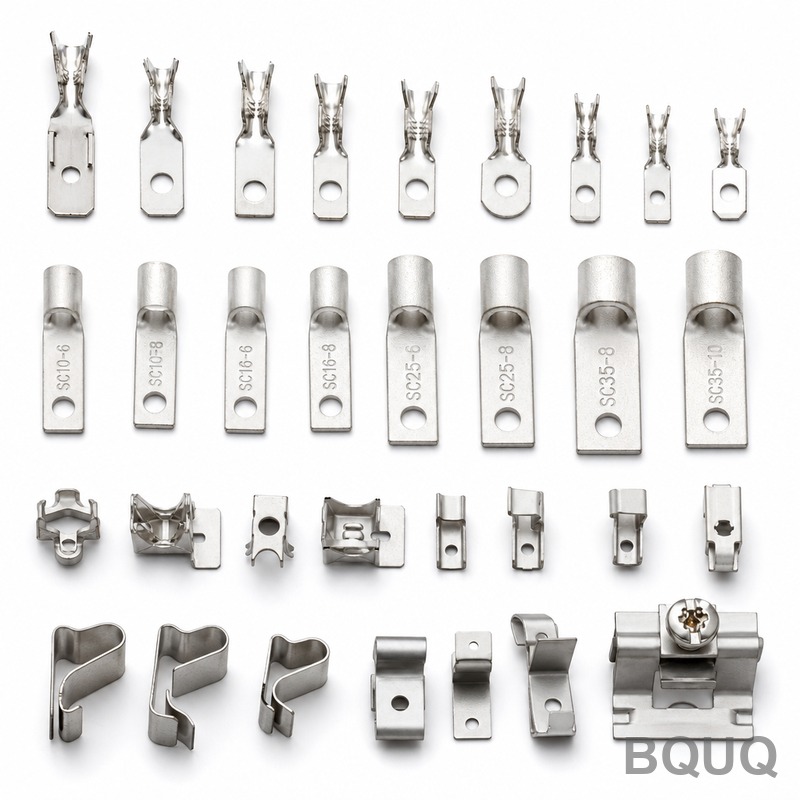
How to Inspect Stamped Parts: Key Dimensions and Quality Checks for Precision Manufacturing
In precision metal stamping, inspection is not a final gate but a continuous feedback loop that governs die wear, material consistency, and press stability. The direct answer to how you inspect stamped parts is to verify critical-to-function (CTF) dimensions using calibrated tools, validate material hardness and surface integrity, and compare results against a statistical process control (SPC) baseline derived from first-article inspection (FAI). For a 0.5 mm thick stainless steel part, this means holding a flatness tolerance of 0.05 mm and a hole position of ±0.05 mm, which requires a combination of optical measurement, coordinate measuring machines (CMM), and go/no-go fixtures.
Critical Dimensions: What to Measure First
Not all dimensions carry equal weight. In stamped parts, the blank edge, bend radius, hole diameter, and material thickness dictate assembly fit and structural integrity. Focus on these four categories:
1. Hole diameter and position: For precision holes under 3 mm, tolerance is typically ±0.03 mm. Use a pin gauge set or a vision system with backlighting to avoid edge deformation from manual calipers. 2. Bend angle and springback: After bending, springback ranges from 1 to 3 degrees for cold-rolled steel (CRS) and 2 to 5 degrees for stainless steel 304. Measure with a digital protractor or optical comparator at 10x magnification. 3. Flatness and twist: For heat sink baseplates, flatness must be within 0.1 mm over a 100 mm span. A surface plate with a dial indicator at 5 fixed points is the standard method. 4. Burr height: Maximum allowable burr for functional edges is 0.05 mm for automotive-grade parts, but 0.02 mm for medical or electronic contacts. Measure with a burr gauge or a profilometer.
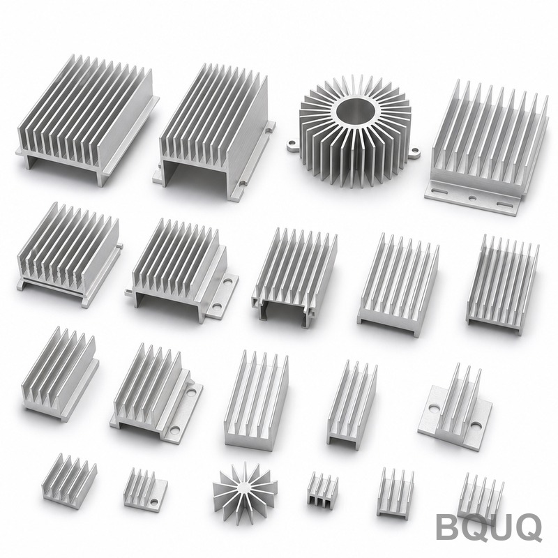
Example: A stamped copper heat sink (2 mm thick) requires hole position of ±0.1 mm and flatness of 0.08 mm. A CMM with a touch probe at 21 points will verify this in under 90 seconds per part.
Measurement Tools and Their Accuracy Limits
Selecting the wrong tool introduces more error than the manufacturing process itself. Below is a practical comparison of tools used for stamped part inspection, with their resolution and typical application range.
| Tool Type | Resolution | Typical Tolerance Range | Application Example |
| Digital Caliper | 0.01 mm | ±0.05 mm or looser | Outer length, width, thickness |
| Micrometer | 0.001 mm | ±0.01 mm | Material thickness, small diameters |
| Optical Comparator | 0.005 mm | ±0.02 mm | Profile, bend angle, radius |
| CMM (Touch Probe) | 0.001 mm | ±0.01 mm | True position, 3D datums |
| Pin Gauge Set | 0.002 mm | Go/No-Go | Hole diameter under 5 mm |
| Surface Roughness Tester | 0.001 µm Ra | Ra 0.4 to 3.2 µm | Contact surfaces, sealing areas |
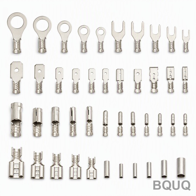
For high-volume production (over 10,000 parts per day), manual measurement of every part is not feasible. Instead, use a sampling plan per ISO 2859-1 with an AQL of 0.65 for critical dimensions and 1.5 for cosmetic features. A typical first-off inspection after die setup takes 45 minutes, followed by in-process checks every 2 hours.
In-Process vs. Final Inspection: Where to Catch Defects
In-process inspection prevents scrap, while final inspection protects the customer. For progressive die stamping, in-process checks should occur at the coil feed, after the pilot hole piercing, and after the final forming station.
- Coil feed: Verify material thickness with a micrometer. A variation of 0.02 mm from nominal can cause die jamming or excessive burr. - Piercing station: Check pilot hole diameter with a go/no-go pin. If the pin does not pass, the die is dull and requires sharpening. Typical die life for a pierce punch in 1.2 mm CRS is 500,000 strokes before a 0.01 mm wear occurs. - Final forming: Measure bend angle with a protractor. If springback exceeds the predicted 2 degrees, increase the over-bend angle by 0.5 degrees and re-run.
Final inspection at BQUQ includes a 100% check for burr direction, surface scratches deeper than 0.03 mm, and plating thickness (if applicable). For zinc-nickel plating, a thickness of 8 to 12 µm is verified with an X-ray fluorescence (XRF) gauge, which costs approximately 15,000 USD but ensures salt spray resistance of 120 hours per ASTM B117.
Statistical Process Control and Data Recording
You cannot improve what you do not measure. For stamped parts, implement SPC on the three most critical dimensions. Collect 5 consecutive parts every 30 minutes and plot the average and range on an X-bar and R chart.
Control limits should be set at ±3 sigma. For example, if the hole position has a standard deviation of 0.008 mm, the upper control limit is the nominal plus 0.024 mm. If a measurement exceeds this, stop the press immediately. The cost of stopping production for 30 minutes is roughly 150 USD in lost output, but the cost of shipping 1,000 defective parts is over 2,000 USD in rework and logistics.
Data recording should be digital, not paper. Use a spreadsheet or a dedicated SPC software that logs time stamps and operator IDs. At BQUQ, we archive inspection data for 10 years per ISO 9001:2015 requirements. This traceability is critical for automotive (IATF 16949) and medical (ISO 13485) certifications.
Common Defects and Root Cause Analysis
The following table lists frequent stamped part defects, their probable causes, and the specific inspection method to detect them.
| Defect Type | Probable Root Cause | Inspection Method | Acceptable Limit |
| Excessive Burr | Dull punch or die clearance too wide | Burr gauge or microscope at 20x | 0.05 mm max |
| Springback Variation | Material hardness inconsistency | Optical comparator + hardness tester | ±1 degree from spec |
| Surface Scratch | Foreign debris on die or worn guide pins | Visual inspection under 5x light | Depth under 0.03 mm |
| Dimensional Drift | Thermal expansion of die (heat buildup) | CMM every 2 hours | ±0.05 mm from nominal |
| Thin Wall or Crack | Wrong material grade or press speed too high | Tensile test on sample coupon | Elongation over 20% |
For example, if burr height increases from 0.02 mm to 0.07 mm over 300,000 strokes, the die clearance (typically 10% of material thickness) has worn by 0.01 mm. The corrective action is to regrind the punch and replace the die button, which costs about 80 USD in tooling and 2 hours of downtime.
Practical Tips for Inspection Efficiency
Inspection should be fast, repeatable, and documented. Here are five engineering tips to streamline your stamped part quality checks.
First, design dedicated go/no-go gauges for high-volume parts. A functional gauge that checks hole position and outer profile simultaneously costs 300 to 500 USD but reduces inspection time from 2 minutes to 15 seconds per part. Second, calibrate all measuring tools every 12 months or after 500 hours of use, whichever comes first. A digital caliper drifting by 0.02 mm will cause false rejects or missed defects.
Third, perform a first-article inspection (FAI) on the first 5 parts of every new batch, not just the first part. This catches die temperature stabilization effects. Fourth, use a temperature-controlled inspection room at 20 degrees Celsius plus or minus 1 degree. Steel expands at 11.5 x 10^-6 per degree Celsius, meaning a 100 mm part changes by 0.001 mm per degree. In a factory at 30 degrees Celsius, this introduces a 0.01 mm error.
Finally, train operators to inspect at the press, not at a separate lab. Immediate feedback reduces the response time to a defect from 20 minutes to 2 minutes. A simple rule: if a dimension is out of tolerance, check the last 50 parts and segregate them for rework.
Conclusion
Inspecting stamped parts is a systematic process of measuring critical dimensions, controlling tool wear, and recording data for statistical analysis. The key is not to inspect everything with maximum precision, but to identify the 20% of dimensions that cause 80% of functional failures. By using the correct tools, setting realistic tolerances, and implementing SPC, you can reduce defect rates to below 500 parts per million (PPM) and maintain a 99.5% on-time delivery rate.
At BQUQ, we have applied these methods for 20 years across CNC machining, metal stamping, springs, and heat sinks. Our quality team uses calibrated CMMs and optical comparators on every batch, and we provide a full inspection report with each shipment. If you need a stamped part inspected or manufactured to tight tolerances, contact us for a free engineering review.
For a detailed quote within 12 hours, email your 2D or 3D drawing to sc@bquq.com. You can also reach us on WhatsApp at +86 13713157787 or visit www.bquq.com for our capability matrix and quality certifications. We respond to every inquiry with a technical assessment, not just a price.
Related Articles
- Springback Compensation in Metal Stamping: Design & Simulation Guide
- Multi-Physics Coupled Failure Mechanisms and Systematic Prevention Strategies in Stamping Processes
- High-speed precision stamping and in-die microforming technology: from electronic connections to micromotor cores
Frequently Asked Questions
What are the most critical dimensions to inspect on a stamped metal part?
The four priority categories are hole diameter and position, bend angle and springback, flatness and twist, and burr height. For holes under 3 mm, tolerance is typically ±0.03 mm. Bend springback ranges from 1-3 degrees for cold-rolled steel and 2-5 degrees for stainless steel 304. Flatness must be within 0.1 mm over a 100 mm span for heat sink baseplates, and maximum burr is 0.05 mm for automotive parts or 0.02 mm for medical/electronic contacts.
Which measurement tools are recommended for inspecting stamped parts, and what are their accuracy limits?
Recommended tools include digital calipers (resolution 0.01 mm, suitable for ±0.05 mm or looser), micrometers (0.001 mm, for ±0.01 mm tolerances), optical comparators (0.005 mm, for profiles and angles), CMMs with touch probes (0.001 mm, for true position and 3D datums), pin gauges (0.002 mm, for holes under 5 mm), and surface roughness testers (0.001 µm Ra, for Ra 0.4-3.2 µm). Choosing the wrong tool can introduce more error than the manufacturing process.
How do you inspect a stamped copper heat sink for hole position and flatness?
For a 2 mm thick copper heat sink requiring hole position of ±0.1 mm and flatness of 0.08 mm, a CMM with a touch probe is used. It verifies these dimensions by measuring 21 points on the part, completing the inspection in under 90 seconds per part. This method ensures accurate 3D measurement of true position and flatness across the baseplate.
What sampling plan is used for high-volume stamped part production?
For production over 10,000 parts per day, manual inspection of every part is not feasible. We follow ISO 2859-1 sampling with an AQL of 0.65 for critical dimensions and 1.5 for cosmetic features. A first-off inspection after die setup takes 45 minutes, followed by in-process checks every 2 hours to maintain quality control.


