
How to Measure a Compression Spring: Key Dimensions and Formulas
To measure a compression spring accurately, you must record four critical dimensions: wire diameter (d), outside diameter (OD), free length (L₀), and total number of coils (Nt). The key formulas derived from these measurements include spring rate (k = Gd⁴ / 8D³Nₐ), solid height (Hs = Nt × d), and maximum shear stress (τ = 8FD / πd³). For precision manufacturing applications, always use a calibrated digital caliper with 0.01 mm resolution and a flat surface plate for length measurement, as errors exceeding ±0.05 mm in wire diameter can alter spring rate by up to 4%.
What Tools Are Required for Accurate Compression Spring Measurement?
The minimum tool set for compression spring inspection includes a digital caliper (resolution 0.01 mm, accuracy ±0.02 mm), a micrometer (resolution 0.001 mm for wire diameter), and a surface plate with a height gauge. For production environments, an optical comparator or CMM (coordinate measuring machine) is recommended for measuring coil pitch and free length with tolerances of ±0.01 mm. A spring testing machine with a load cell accuracy of ±0.5% of reading is essential for verifying the actual spring rate, and it should be calibrated at least once every 12 months per ISO 376 standards.
Which Dimensions Define a Compression Spring's Geometry?
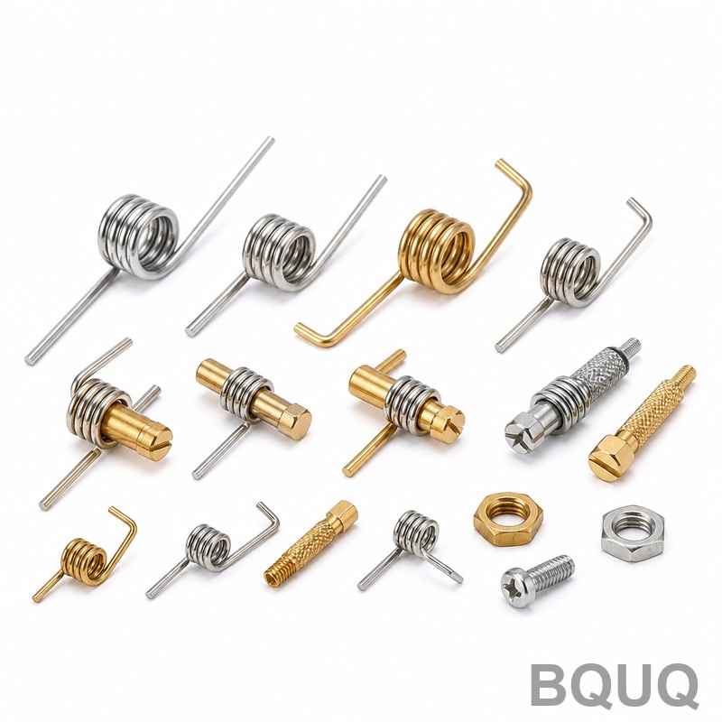
A compression spring has five primary geometric dimensions that must be measured and recorded on every inspection report. Wire diameter (d) is the thickness of the wire itself, typically ranging from 0.1 mm to 20 mm in industrial springs. Outside diameter (OD) is the widest point across the coils, while inside diameter (ID) is calculated as OD minus 2d, and mean diameter (D) equals OD minus d. Free length (L₀) is the overall length with no load applied, measured along the spring's central axis. Total coils (Nt) includes all coils from tip to tip, while active coils (Na) are those that actually deflect under load, typically Nt minus 2 for closed and ground ends.
How Do You Measure Wire Diameter and Outside Diameter Correctly?
For wire diameter, use a micrometer with a ratchet stop and measure at three different locations along the spring body, rotating the spring 120 degrees between readings. Take the average of three readings and record the minimum value, as the thinnest point determines the stress concentration. For outside diameter, measure at three positions: near both ends and at the middle, using calipers with the jaws parallel to the coil axis. The OD tolerance for a spring with 10 mm nominal OD is typically ±0.15 mm for general applications, but precision springs (BQUQ Class A) hold ±0.05 mm. Never measure OD across the coil gap, as this introduces errors up to 0.3 mm.
How Is Free Length Measured and Why Does It Matter?
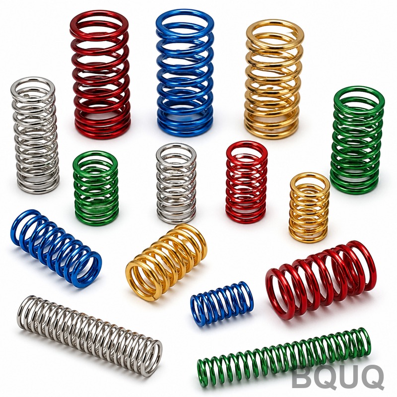
Free length (L₀) is measured with the spring resting on a flat surface plate under its own weight, using a height gauge or digital indicator. The spring must be oriented with its axis perpendicular to the plate, and you should measure at the highest point of the top coil. For springs longer than 50 mm, support the spring vertically to avoid bowing, which can introduce measurement errors of 0.5 mm or more. Free length directly determines the spring's installed height and preload; a 1 mm error in free length on a spring with rate 10 N/mm will change the preload force by 10 N, which can be 20% of the required load.
Which Formulas Convert Measured Dimensions into Spring Rate and Stress?
The most important formula is the spring rate equation: k = (G × d⁴) / (8 × D³ × Na), where G is the shear modulus (79,300 MPa for music wire ASTM A228, 77,200 MPa for stainless steel 302). For example, a spring with d = 2.0 mm, D = 12 mm, Na = 8, using music wire, has k = (79300 × 16) / (8 × 1728 × 8) = 1,268,800 / 110,592 = 11.47 N/mm. Solid height is calculated as Hs = Nt × d, which for a spring with 10 coils and 2 mm wire equals 20 mm. Maximum shear stress at solid height is τ = (8 × F × D) / (π × d³), and this value must not exceed 45% of the material's tensile strength for static applications.
What Tolerances Should You Expect for Different Spring Classes?
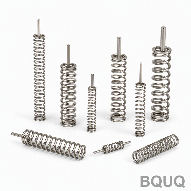
Precision compression springs manufactured by CNC coiling machines achieve tighter tolerances than standard springs, but the achievable values depend on the spring index (D/d ratio). For a spring index between 4 and 12, the typical tolerance classes per DIN 2095 are shown in the table below. These values represent the standard for industrial springs; BQUQ offers Class 1 tolerances as standard and Class 2 on request with a 10% cost premium. The tolerance for free length is the largest relative value, often ±1.5% for Class 1, because it is affected by coil count and wire diameter variations.
| Dimension | Class 1 (Precision) | Class 2 (General) | Measurement Tool | Typical Cost Impact |
| Wire diameter (d) | ±0.01 mm | ±0.02 mm | Micrometer 0.001 mm | +8% for Class 1 |
| Outside diameter (OD) | ±0.15 mm | ±0.30 mm | Digital caliper | +5% for Class 1 |
| Free length (L₀) | ±1.0% or ±0.15 mm | ±2.0% or ±0.50 mm | Height gauge | +10% for Class 1 |
| Spring rate (k) | ±3.0% | ±5.0% | Spring tester | +12% for Class 1 |
| Solid height (Hs) | ±0.10 mm | ±0.25 mm | Caliper | Included |
How Do You Verify the Spring Rate with a Load Test?
To verify spring rate, compress the spring to 20% of its deflection range and record the load, then compress to 80% of the range and record the second load. The measured rate is (F₂ - F₁) / (L₂ - L₁), where L₁ and L₂ are the corresponding lengths. For a spring with 10 mm total deflection, test at 2 mm and 8 mm compression, ensuring the spring is fully seated but not reaching solid height. The load measurement must be taken after a 5-second settling period to allow for stress relaxation. If the measured rate deviates from the calculated value by more than 3%, re-check the wire diameter and active coil count, as these are the most common sources of error.
When Should You Measure Both Inside Diameter and Free Length Over Time?
Inside diameter (ID) must be measured when the spring operates over a rod, as a tight ID causes friction and premature wear, while a loose ID leads to buckling. The ID tolerance is typically ±0.10 mm for Class 1, and you should verify that ID clearance is at least 1% of the rod diameter. Free length should be re-measured after every 100,000 cycles in fatigue applications, as compression springs can lose 2-5% of their free length due to settling, especially when stressed above 30% of tensile strength. For springs operating at temperatures above 150°C, measure free length at operating temperature and at room temperature, as thermal expansion of steel is approximately 12 × 10⁻⁶ per °C, which changes length by 0.12 mm for a 100 mm spring at a 100°C rise.
FAQ
What Is the Difference Between Total Coils and Active Coils?
Total coils (Nt) is the complete count of all coils including the end coils, while active coils (Na) are the coils that actually deflect under load. For closed and ground ends, subtract 2 from the total count; for closed ends not ground, subtract 1.5; for open ends, subtract 1. The active coil count directly affects the spring rate formula, so an error of one coil changes the rate by approximately 12%.
Can I Measure a Compression Spring with a Ruler Instead of a Caliper?
A standard ruler is only acceptable for free length measurement on springs longer than 50 mm with tolerances greater than ±0.5 mm. For wire diameter, outside diameter, and solid height, a ruler introduces errors of 0.3-0.5 mm, which is unacceptable for any precision spring application. Invest in a digital caliper costing approximately $30-80 USD for production inspection; the cost is justified by preventing rejected parts.
How Do I Calculate the Spring Rate if I Only Know the Wire Diameter and OD?
If you know wire diameter (d), outside diameter (OD), and total coils (Nt), first calculate mean diameter D = OD - d, then estimate active coils Na = Nt - 2 for closed ends. Use the formula k = (G × d⁴) / (8 × D³ × Na) with G = 79,300 MPa for music wire. For example, d = 1.5 mm, OD = 12 mm, Nt = 8 gives D = 10.5 mm, Na = 6, and k = (79300 × 5.06) / (8 × 1157.6 × 6) = 401,258 / 55,565 = 7.22 N/mm.
What Is the Minimum Number of Measurements Required for a Reliable Inspection?
For production inspection, measure wire diameter at 3 points, outside diameter at 3 positions, free length once, and total coils by counting twice. For the spring rate verification, perform one load test at two deflection points. This gives a total of 9 individual data points per spring, which statistically covers 95% of common manufacturing variations in CNC-coiled springs.
Why Does My Measured Spring Rate Differ from the Calculated Value?
The most common reasons are an incorrect shear modulus (using 79,300 instead of 77,200 MPa for stainless steel), an error in counting active coils, or wire diameter variation exceeding tolerance. Also, check that the spring index (D/d) is above 4, as lower indices cause stress concentration and non-linear behavior. If the measured rate differs by more than 5%, measure the wire diameter again with a micrometer at the thinnest cross-section, as the nominal value may not reflect the actual minimum.
How Often Should I Calibrate My Measurement Tools?
Digital calipers and micrometers should be calibrated every 12 months with a gauge block set, per ISO 17025 requirements. Spring testing machines require calibration every 6 months using certified reference springs with known rates traceable to national standards. For critical aerospace or medical springs, calibrate before every production batch, and record the calibration date and results in the inspection report.
What Is the Best Way to Measure a Spring That Is Already Installed in an Assembly?
If the spring is compressed in an assembly, measure the installed length with a depth gauge and subtract the known preload deflection to calculate free length. For wire diameter, measure the spring ends if accessible, or use the documented material certificate from the supplier. Never measure an installed spring's free length by removing it from the assembly, as this alters the settling characteristics and invalidates the stress-relief treatment.
To ensure your compression springs meet design specifications, BQUQ recommends providing the measured dimensions and target spring rate on your RFQ. Our engineering team can reverse-engineer a spring from your sample within 48 hours, providing a full dimensional report with tolerance analysis. For a free measurement consultation and quoting within 12 hours, contact us at sc@bquq.com or WhatsApp +86 13713157787. Visit www.bquq.com to download our spring inspection checklist and calculation spreadsheet.


