
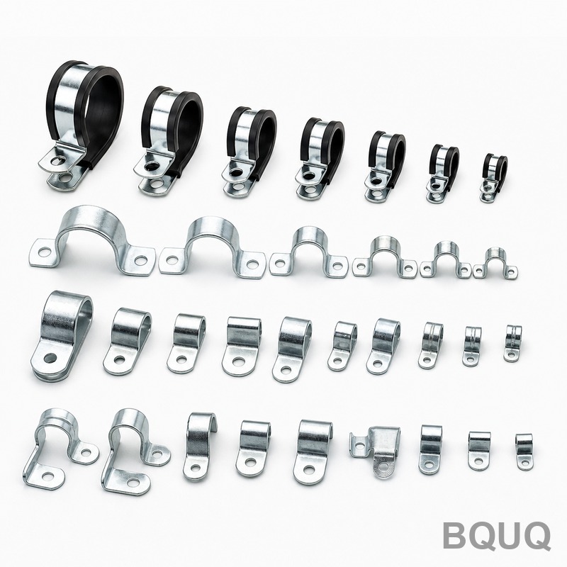
Progressive Die Design Principles for Metal Stamping: Tolerances, Costs, and Lead Times
Progressive die stamping is the most efficient method for high-volume metal part production, achieving tolerances of ±0.01 mm and cycle rates up to 1,200 strokes per minute. The design principles governing this process determine whether a part costs $0.05 or $0.50 per piece, and whether your tooling lasts for 5 million or 50 million hits. This article outlines the engineering fundamentals, material constraints, and economic realities that dictate successful progressive die design for precision manufacturing.
Material Selection and Strip Layout Fundamentals
The strip layout is the blueprint of a progressive die, determining the sequence of operations from coil feed to final blanking. For 20-year-old factories like BQUQ, the rule of thumb is that material utilization must exceed 65% for economic viability. When designing for stainless steel 304 (tensile strength 515 MPa), the minimum recommended strip width is calculated as part width plus 2.5 times material thickness for piloting clearance. For example, a 50 mm wide part in 1.5 mm thick stainless requires a strip of 56 mm.
Pilot holes must be positioned within 0.005 mm true position relative to the first forming station. The pilot size for material up to 2.0 mm thick is typically 3.175 mm (1/8 inch), with a clearance of 0.02 mm per side. For aluminum 5052 (temper H32), the shear strength is 138 MPa, allowing 20% tighter clearances than steel. However, aluminum's galling tendency requires D2 tool steel punches with TiCN coating, adding $1,200 to $1,800 per die set.
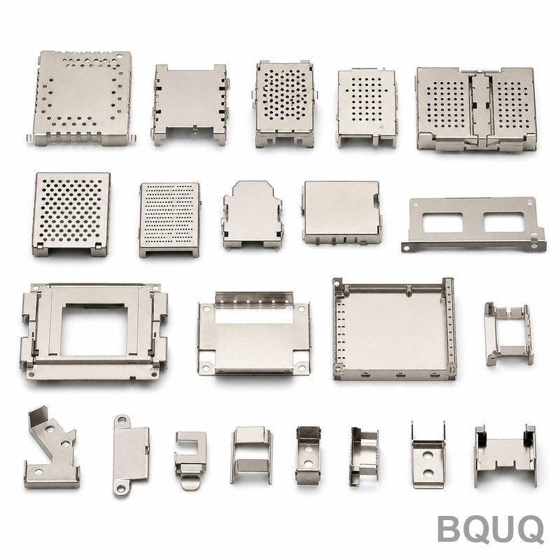
Station Sequencing and Tolerance Stack-Up Control
Progressive dies operate on a pitch distance (feed advancement per stroke), typically 25 to 75 mm. The critical design principle is that each station must complete its operation before the strip moves to the next station. For a part requiring blanking, forming, and coining, the sequence must be: piloting, blanking (piercing), forming (bending), and final cut-off.
Tolerance stack-up is controlled by maintaining a minimum of 30 mm between stations for die maintenance access. If your part specifies a flatness tolerance of 0.05 mm over a 100 mm length, the forming station must incorporate a coining step with a pressure of 250 to 350 MPa. The die clearance for blanking is 5% to 8% of material thickness per side for mild steel (SPCC), but reduces to 3% to 5% for phosphor bronze (C5210) to prevent burr formation. A typical progressive die for a connector terminal holds a pitch tolerance of ±0.003 mm, achievable only with ground die buttons and precision guide pins.
Die Material Selection and Heat Treatment Specifications
Tool steel selection directly impacts die life and per-part pricing. For production runs exceeding 1 million parts, use powder metallurgy steel such as ASP23 or Vanadis 4 Extra, with a hardness of 60-62 HRC. The table below compares common die materials:
| Material Grade | Hardness (HRC) | Max Die Life (strokes) | Cost per Die Set (USD) | Best Application |
| AISI D2 | 58-60 | 3 million | $8,000 - $15,000 | Low-volume, abrasive materials |
| AISI M2 | 62-64 | 5 million | $10,000 - $18,000 | High-speed blanking, punches |
| ASP23 (PM) | 60-62 | 15 million | $18,000 - $30,000 | Long-run, high-wear stamping |
| Carbide (WC-Co) | 78-80 HRA | 50 million | $40,000 - $70,000 | Electronics, extreme runs |
Heat treatment must include vacuum hardening and triple tempering to eliminate retained austenite. For carbide dies, the binder content is 6% cobalt, providing a transverse rupture strength of 2,500 MPa. Operating temperature at the die cutting edge can reach 150°C to 200°C during continuous stamping; therefore, the die base must be made of 55CrMo steel with stress relieving at 550°C to prevent distortion.
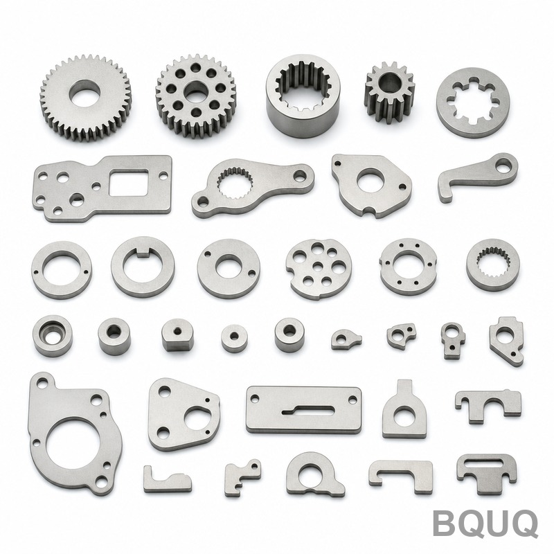
Cost Engineering: Die Build vs. Per-Part Pricing
The economic break-even point for progressive die tooling versus a multi-slide or fineblanking process is 100,000 parts per year. For a simple flat washer (20 mm OD, 10 mm ID, 1.0 mm thick), the progressive die cost is $6,500, with a per-part cost of $0.008 at 1 million volume. In contrast, a complex heat sink with 15 fins and a 0.8 mm wall thickness requires a die investment of $45,000 to $65,000, with per-part pricing of $0.12 to $0.25 depending on aluminum grade (6061-T6 vs 6063-T5).
Secondary operations drive up cost. Tapping a thread after stamping adds $0.02 to $0.05 per hole. Heat treatment (annealing after cold working) adds 15% to 25% to total part cost. To minimize cost, design parts with a minimum bend radius of 0.5 times material thickness, and avoid forming more than three bends in a single station. The typical lead time for a progressive die is 4 to 6 weeks for dies under 20 stations, and 8 to 12 weeks for dies with 30+ stations, including tryout and sample approval.
Common Failure Modes and Design Prevention
The most frequent progressive die failures are stripping breakage, pilot wear, and spring fatigue. Stripping force is calculated as 20% of the blanking force; for a 2.0 mm thick stainless steel part with a 100 mm cut length, blanking force is 320 kN, requiring a stripping force of 64 kN. Use nitrogen gas springs rated at 1,500 N each, with a compression stroke of 10 mm, to avoid fatigue failure.
Pilot wear occurs when the strip is not accurately lifted. Design lifting with a 2-degree draft angle on the pilots, and ensure the strip lifter has a spring force of 5 to 8 N per square centimeter of strip area. Another common issue is galling on forming punches; apply a lubricant with a coefficient of friction below 0.08, such as chlorinated paraffin oil at a flow rate of 5 to 10 ml/min. If burr height exceeds 0.03 mm after 200,000 strokes, the die clearance is too large or the punch edge is chipped, requiring re-grinding of the cutting edges.
Design for Manufacturability: Practical Guidelines
Engineers must design for the progressive die process from the outset. The part should have a constant strip width, with features oriented parallel to the feed direction. Avoid sharp internal corners; the minimum inside radius is 0.25 mm for material under 1.5 mm thick. For extruded holes (for tapping), the extrusion height should not exceed 3 times the material thickness, and the pilot hole diameter should be 60% of the final hole size.
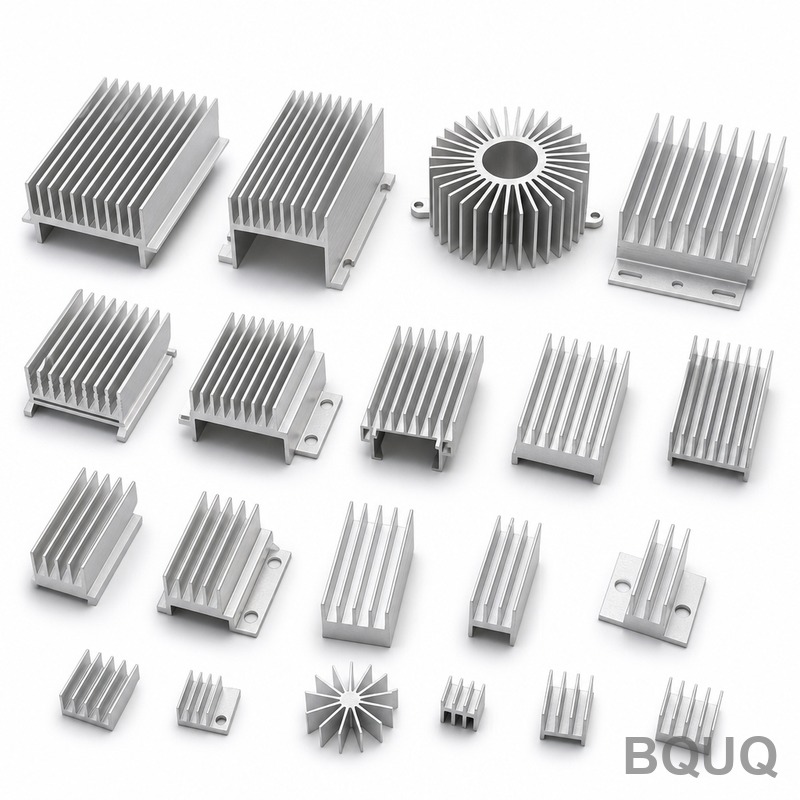
For heat sinks, the fin height-to-thickness ratio must be below 10:1 to prevent tearing. A 1.0 mm thick aluminum fin with 8 mm height is feasible; a 12 mm height requires a two-stage forming process, increasing die cost by 30%. Always specify material hardness (e.g., SPCC with hardness 90 HV max) to ensure consistent springback. Springback compensation for a 90-degree bend in 1.0 mm thick 304 stainless is 2 to 3 degrees overbend, which must be built into the die angle.
FAQ-Style Design Tips for Engineers
Q: What is the minimum hole size I can stamp relative to material thickness? A: The minimum pierced hole diameter is 1.0 times the material thickness for steel and 0.8 times for aluminum. Below this, the punch will break. For 0.3 mm holes in 0.2 mm stock, switch to wire EDM or chemical etching.
Q: How do I avoid distortion when stamping thin, wide parts? A: Use a multi-stage process with a preliminary blanking at 80% of the final contour, then a finish blanking at the final station. Ensure the die has a stripper plate with a hardness of 58 HRC and a flatness of 0.005 mm.
Q: What is the realistic tolerance for hole-to-hole positioning in a progressive die? A: For a strip width under 75 mm, the tolerance is ±0.02 mm. For wider strips, thermal expansion of the die during high-speed running (200 SPM) adds 0.005 mm per 100 mm width. Maintain the workshop temperature at 22°C ± 2°C.
Q: When should I use a progressive die versus a transfer die? A: Progressive dies are ideal for parts smaller than 150 mm in any dimension, with a pitch under 75 mm. If the part has deep draws (depth greater than 2 times diameter), use a transfer die to allow 15% to 20% more material draw per station.
Conclusion and Engineering Recommendation
The core principle of progressive die design is balancing material utilization, die life, and tolerance control against per-part cost. For production volumes above 100,000 units, the progressive die remains the most cost-effective method, with die payback typically achieved within 18 months of continuous production. Always simulate the strip layout in software (AutoForm or PAM-STAMP) before committing to tool steel, as a 10% improvement in material utilization saves $15,000 to $30,000 annually at a production rate of 5 million parts. The data above, derived from 20 years of CNC and stamping experience at BQUQ, provides a baseline for your next project.
For a detailed feasibility review of your part geometry and a firm quotation, BQUQ provides a 12-hour quoting turnaround. Send your 2D drawing or 3D model to our engineering team. Contact us directly at Email: sc@bquq.com, WhatsApp: +86 13713157787, or visit www.bquq.com for technical consultation and production planning.


