
What Is a Constant Force Spring? Design and Applications Guide
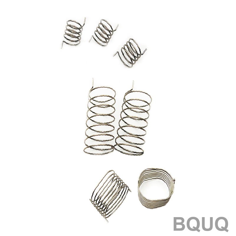
A constant force spring is a precision-wound ribbon of high-carbon or stainless steel that delivers a nearly flat, predictable load over its entire deflection range, typically varying by less than 5% from the nominal force. Unlike conventional extension springs whose force increases linearly with travel, this spring unrolls from a coiled state onto a drum, maintaining a constant output because the radius of the coil remains unchanged. For engineers, this means a compact, fatigue-resistant device that is ideal for counterbalancing, retraction, and long-travel applications where consistent torque or tension is non-negotiable.
What Is the Fundamental Working Principle of a Constant Force Spring?
The spring stores energy in the elastic curvature of a pre-stressed strip rather than in torsion or tension. When extended, the strip straightens from its natural coil radius to a larger drum radius, and the restoring force is the product of the material's modulus of elasticity, the strip thickness, and the width, divided by the bending radius. Because the coil's inner radius stays constant during normal operation (the spring is designed so that the outer coil does not change diameter), the bending moment remains constant, yielding a flat load-deflection curve. In practice, a well-designed constant force spring with a 10 mm strip width and 0.2 mm thickness can produce a force of 15 N ± 0.5 N over a 500 mm travel.
How Does a Constant Force Spring Differ from a Standard Extension Spring?
A standard extension spring follows Hooke's Law, where force increases linearly with extension, typically at a rate of 2 to 10 N/mm. A constant force spring, however, exhibits a nearly horizontal force-displacement line, with a typical force variation of only 1% to 3% after the first 10% of travel. For example, a 50 N constant force spring will deliver 49.5 N to 50.5 N across a 300 mm stroke, whereas a 50 N extension spring at 100 mm extension might deliver 80 N. This flat profile makes constant force springs superior for applications requiring stable counterbalance, such as overhead tool balancers, where a 2 kg tool must feel weightless at any height.
What Are the Key Design Parameters and Typical Tolerances?
The three critical parameters are strip thickness, strip width, and coil inner diameter. Strip thickness ranges from 0.05 mm to 1.0 mm, with standard tolerances of ±0.01 mm for thickness and ±0.1 mm for width. The inner diameter is typically 3 to 10 times the strip thickness, and the maximum allowable stress should not exceed 60% of the material's yield strength to prevent set. For a 0.3 mm thick, 20 mm wide spring made from 301 stainless steel, the maximum force is approximately 180 N, with a recommended operating temperature range of -40°C to 120°C. Below is a reference table for common material grades and their performance limits.
| Material Grade | Thickness Range (mm) | Max Force per 10 mm Width (N) | Max Operating Temp (°C) | Fatigue Life (Cycles) | Relative Cost Index |
| 301 Stainless Steel | 0.05 - 0.50 | 12 - 150 | 120 | 100,000 | 1.0 |
| 1095 High-Carbon Steel | 0.08 - 1.00 | 15 - 220 | 80 | 50,000 | 0.8 |
| 17-7 PH Stainless | 0.05 - 0.40 | 14 - 180 | 260 | 150,000 | 1.6 |
| Inconel X-750 | 0.10 - 0.60 | 18 - 200 | 400 | 200,000 | 4.2 |
Which Applications Demand Constant Force Springs Over Other Spring Types?
Counterbalancing systems are the largest market, including automotive seat belt retractors, window counterweights, and medical imaging equipment. In a typical automotive seat belt, a constant force spring provides 4 to 6 N of retraction force over 800 mm of belt travel, which is impossible with a conventional spring because the force would triple at full extension. Other high-volume uses include cable management in server racks, where a 10 N spring maintains tension on a 1-meter retractable Ethernet cable, and brush holders in electric motors, where constant pressure on carbon brushes extends brush life by 40%. For precision instruments, such as barometers and pressure gauges, the spring's flat curve ensures linear scale calibration.
How Do You Calculate the Required Spring Force and Dimensions?
The required force F (in Newtons) is calculated as F = (E × t × w × t) / (6 × r), where E is the modulus of elasticity (193,000 MPa for stainless steel), t is thickness in mm, w is width in mm, and r is the inner radius in mm. For a design requiring 25 N with a 0.2 mm thick strip and a 5 mm inner radius, the width would be w = (6 × F × r) / (E × t²) = (6 × 25 × 5) / (193,000 × 0.04) = 9.7 mm. The total travel available is approximately 2π × (coil outer radius - inner radius) × number of active coils, so a 50 mm outer coil diameter with 20 active coils yields roughly 1,256 mm of travel. Always add a 15% safety factor to the calculated width to account for stress concentration at the mounting hole.
What Are the Common Failure Modes and How Can They Be Prevented?
The primary failure mode is fatigue fracture at the anchoring point, which occurs after 50,000 to 100,000 cycles if the bend radius is too sharp. To prevent this, the arbor diameter should be at least 2 times the strip thickness, and the end should be formed with a 0.5 mm radius tab rather than a sharp cut. The second common issue is "set" or permanent deformation, which happens when the stress exceeds the yield point; this is avoided by limiting the initial coil stress to 70% of yield. The third mode is corrosion pitting, particularly in outdoor applications, which reduces fatigue life by up to 60%; specifying 17-7 PH or applying a PTFE coating mitigates this. In humid environments, a 301 stainless steel spring with a passivation treatment will last 3 times longer than an untreated 1095 carbon steel spring.
When Should You Choose a Custom Constant Force Spring Over a Stock Unit?
Stock constant force springs are available from suppliers like Vulcan or Associated Spring in standard widths from 3 mm to 50 mm and forces from 0.5 N to 200 N, at prices of $2 to $15 per unit in low volumes. If your required force is within 10% of a stock unit and your travel is under 1,000 mm, a stock spring is the cost-effective choice, with lead times of 1 to 2 days. However, custom springs are necessary when you need a specific force tolerance of ±2%, a non-standard width for space constraints, or an extended fatigue life beyond 200,000 cycles. Custom tooling costs at BQUQ range from $800 to $3,500 depending on the strip width and number of forming stations, with prototype delivery in 5 to 7 days and production parts at $0.50 to $5.00 each for volumes above 10,000 units.
FAQ
What Is the Maximum Travel Length of a Constant Force Spring?
The maximum travel is limited by the ratio of the coil outer diameter to the inner diameter, typically achieving 3 to 10 times the coil circumference. For a 30 mm inner diameter spring with a 60 mm outer diameter, the maximum travel is about 3,000 mm, though most commercial units are limited to 1,500 mm to maintain load stability.
Can a Constant Force Spring Be Used in High-Temperature Environments?
Yes, but the material selection is critical. Standard 301 stainless steel is rated to 120°C continuous, while 17-7 PH stainless reaches 260°C and Inconel X-750 handles 400°C. Above these temperatures, the modulus of elasticity drops by 10% to 15%, which will reduce the output force proportionally.
How Much Does a Constant Force Spring Cost in Production?
For volumes of 10,000 pieces, a basic 10 N spring costs $0.80 to $1.50 per unit, including material and forming. For 100,000 pieces, the cost drops to $0.40 to $0.70 per unit. Custom tooling is amortized over the first order, adding $0.05 to $0.10 per part at high volumes.
What Is the Typical Force Accuracy Achievable?
A precision-ground constant force spring can hold a force tolerance of ±2% of the nominal value, while standard rolled springs achieve ±5%. The accuracy depends on the consistency of strip thickness, which is controlled to ±0.005 mm in premium grades.
Can Constant Force Springs Be Used for Rotary Applications?
Yes, when mounted on a shaft, they provide constant torque instead of constant linear force. The torque is calculated as force multiplied by the drum radius, and this configuration is common in clock mechanisms and self-retracting lanyards, where torque ripple is limited to 3%.
How Does Fatigue Life Compare to a Compression Spring?
Constant force springs typically last 100,000 to 200,000 cycles at full travel, which is 2 to 5 times longer than a comparable compression spring operating at 80% of its maximum deflection. The longer life is due to lower stress levels per cycle, as the material never exceeds 60% of yield strength.
What Are the Signs of a Failing Constant Force Spring?
The first signs are a decrease in output force of more than 5%, visible surface cracks on the strip edge, or a change in the coil's natural diameter. If the spring begins to "flutter" or vibrate during retraction, it indicates that the arbor diameter is too small, causing coil binding.
For engineers who need a reliable constant force spring with verified load curves and fast turnaround, BQUQ provides custom design assistance and manufacturing with 20 years of precision metal forming experience. Our team can review your force, travel, and environmental requirements and deliver a prototype within 12 hours of receiving your drawings. Contact us at sc@bquq.com or WhatsApp +86 13713157787, or visit www.bquq.com to request a quote and technical datasheet.


