
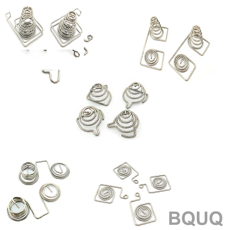
What Is Spring Index and How Does It Affect Spring Design?
The spring index (C) is the ratio of the mean coil diameter (D) to the wire diameter (d), expressed as C = D/d, and it is the single most important geometric parameter for predicting spring stress, manufacturability, and fatigue life. A spring index between 4 and 12 is considered optimal for most compression and extension springs, with values below 4 causing excessive tool wear and values above 12 leading to coil instability and tangling. For precision manufacturing, controlling the spring index within a narrow band is essential for achieving repeatable tolerances of ±0.05 mm on coil diameter and ±1% on free length.
What Is the Exact Formula for Spring Index and Why Does It Matter?
The formula is C = D/d, where D is the mean coil diameter (outer diameter minus wire diameter) and d is the wire diameter. This dimensionless ratio directly determines the curvature correction factor (Kw) in stress calculations, where Kw = (4C – 1)/(4C – 4) + 0.615/C. A spring with C = 5 has a Wahl factor of approximately 1.31, while a spring with C = 10 has a Wahl factor of about 1.14, meaning lower index springs experience significantly higher localized stress at the inner coil surface. The spring index also dictates whether the spring can be coiled on a standard CNC former or requires specialized tooling, as machines are typically set up for a specific D/d ratio range.
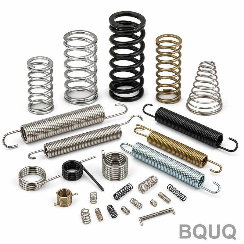
How Does Spring Index Affect Stress and Fatigue Life?
Lower spring index values (C < 4) create sharp bending radii on the wire's inner surface, which concentrates stress and dramatically reduces fatigue life. For example, a compression spring made from 2 mm music wire (ASTM A228) with C = 3 will show a corrected shear stress of 850 MPa at a deflection producing 600 MPa uncorrected stress, compared to only 684 MPa corrected stress for the same wire with C = 8. This 24% stress increase translates to a fatigue life reduction from approximately 1,000,000 cycles to under 100,000 cycles at the same load amplitude. Conversely, springs with C > 12 have lower stress concentration but suffer from lateral buckling (Euler buckling) when compressed beyond 40% of their free length, which causes premature failure and inconsistent load response.
Which Spring Index Range Is Optimal for CNC Coiling and Stamping?
For CNC coiling machines, the practical manufacturing window is C = 4 to C = 14, with the most economical range being C = 5 to C = 10. Below C = 4, the wire must be bent around a mandrel that is less than three times the wire diameter, which causes the inner surface to yield and creates micro-cracks visible under 10x magnification. Above C = 14, the coils tend to separate during the coiling process, requiring additional guide rollers and reducing production speed from 60 parts per minute to about 30 parts per minute. For metal stamping of spring clips and flat springs, the equivalent index concept applies to bend radius over material thickness, with a minimum ratio of 1.5:1 for mild steel and 2.5:1 for hardened stainless steel (301 full hard) to prevent fracture.
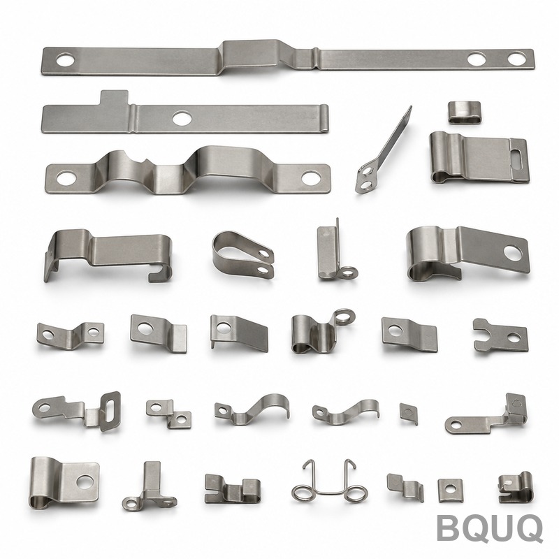
How Does Spring Index Impact Tooling Cost and Production Lead Time?
Tooling cost for CNC coiling is inversely proportional to spring index because lower index springs require carbide tooling with tighter radii and more frequent dressing. A spring with C = 5 requires tooling that costs $1,200 to $1,800 and lasts for 200,000 cycles before reconditioning, while a spring with C = 8 uses standard tooling costing $600 to $900 that lasts 500,000 cycles. For a production run of 100,000 springs, the per-part tooling cost difference is $0.006 for C = 5 versus $0.0018 for C = 8, which becomes significant at high volumes. Lead time for custom tooling on low-index springs is 5 to 7 business days compared to 2 to 3 days for standard index springs, because the carbide blank must be ground with a PCD (polycrystalline diamond) wheel to achieve the required surface finish of 0.4 Ra.
What Tolerances Can Be Achieved with Different Spring Index Values?
The achievable tolerance on mean coil diameter and free length is directly tied to the spring index, as shown in the table below. Higher index springs are easier to control dimensionally because the wire path is more predictable, but they are more sensitive to variations in wire diameter from the mill.
| Spring Index Range | Mean Coil Diameter Tolerance | Free Length Tolerance | Load Tolerance at 50% Deflection | Recommended Wire Diameter Range | Production Speed (parts/min) |
| 3.0 to 4.9 | ±0.10 mm | ±2.0% | ±10% | 0.2 to 3.0 mm | 20 to 40 |
| 5.0 to 8.0 | ±0.05 mm | ±1.0% | ±5% | 0.3 to 10.0 mm | 40 to 60 |
| 8.1 to 12.0 | ±0.08 mm | ±1.5% | ±7% | 0.5 to 12.0 mm | 30 to 50 |
| 12.1 to 16.0 | ±0.15 mm | ±3.0% | ±12% | 1.0 to 8.0 mm | 20 to 30 |
For a compression spring with C = 6 and a mean diameter of 12 mm, the tolerance is ±0.05 mm, which meets most automotive and aerospace specifications. At C = 14, the same mean diameter would have a tolerance of ±0.15 mm, which may still be acceptable for consumer products but fails for precision instruments requiring ±0.03 mm. The load tolerance also degrades because the effective number of active coils is harder to control when the index is high, as slight variations in coil spacing become proportionally larger.
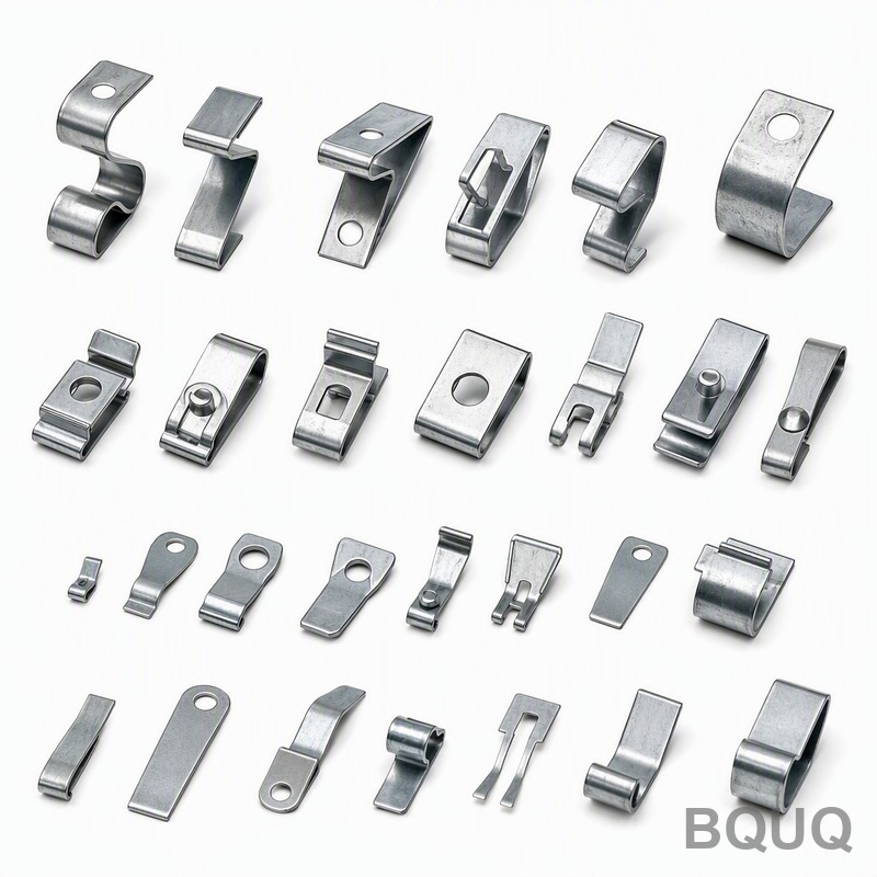
Why Does Spring Index Affect Heat Treatment and Stress Relief?
The spring index determines the residual stress distribution after coiling, which directly influences the stress relief temperature and time. Low-index springs (C < 5) have high residual tensile stress on the inner surface, requiring a stress relief soak at 260°C for 30 minutes for music wire, while high-index springs (C > 10) can be stress relieved at 230°C for 15 minutes. If the stress relief temperature is too high for a low-index spring, the inner surface can recrystallize and lose hardness, dropping the wire from 48 HRC to 44 HRC. For oil-tempered chrome silicon wire (ASTM A401), low-index springs must be stress relieved at 400°C to 425°C, but the soak time must be limited to 20 minutes to avoid over-tempering, which would reduce the maximum service temperature from 230°C to 180°C.
How Should Engineers Select Spring Index for New Designs?
Engineers should start with a target spring index of 7 to 9, which balances stress, manufacturability, and dimensional control, then adjust based on space constraints and load requirements. If the design envelope is tight, reduce the spring index but verify that the corrected shear stress stays below 45% of the wire's tensile strength for static applications, or below 30% for dynamic applications exceeding 100,000 cycles. For example, a spring requiring 50 N at 20 mm deflection with a 10 mm outer diameter and 2 mm wire gives C = 4, which is manufacturable but requires a carbide mandrel and will have a fatigue life of only 50,000 cycles at full deflection; increasing the outer diameter to 12 mm gives C = 5 and doubles the fatigue life. Always specify the spring index on the drawing, not just the coil diameters, because it communicates the intended manufacturing process and prevents the supplier from substituting a different wire diameter.
What Are Common Spring Index Mistakes in Production?
The most common mistake is designing a spring with C = 3.5 to save space, then discovering that the wire breaks during coiling at a rate of 5 to 10 parts per 1,000, which is 20 times higher than the acceptable rate of 0.5 per 1,000. Another frequent error is using a spring index below 4 with square wire, which causes severe corner stress and requires a secondary grinding operation that adds $0.08 to $0.15 per part. A third mistake is ignoring the index when specifying tolerances, such as asking for ±0.03 mm on a spring with C = 14, which forces the manufacturer to use a secondary sizing operation that increases cost by 30% and lead time by 3 days.
FAQ
What Is the Ideal Spring Index for Maximum Fatigue Life?
The ideal spring index for fatigue life is between 6 and 10, where the Wahl correction factor is moderate (1.14 to 1.25) and the coil is stable enough to avoid buckling. At C = 8, the corrected stress is only 12% higher than the uncorrected stress, allowing the spring to achieve over 10 million cycles at 40% of tensile strength. Below C = 4, fatigue life drops by an order of magnitude due to stress concentration.
Can a Spring Have a Spring Index Below 2?
A spring index below 2 is physically impossible to coil on standard equipment because the wire would need to bend around a mandrel smaller than the wire diameter, causing immediate fracture. The practical minimum is C = 3 for spring steel wire up to 3 mm diameter, but even this requires specialized carbide tooling and produces high scrap rates. For C < 3, consider a different geometry such as a Belleville washer or a machined spring.
How Does Spring Index Affect the Load Rate (Stiffness)?
The spring rate (k) is inversely proportional to the cube of the spring index, so a spring with C = 6 has a rate that is (8/6)^3 = 2.37 times higher than a spring with C = 8, assuming the same wire diameter and number of active coils. This means small changes in spring index have a large effect on load, so designers must control C tightly to meet the specified rate within ±5%. For precision springs, the spring index tolerance must be held to ±0.3 to maintain rate control.
Which Wire Materials Are Best for Low Spring Index Springs?
High-tensile materials like music wire (ASTM A228) and chrome silicon (ASTM A401) are best for low index springs because they can tolerate higher corrected stress without yielding. Music wire with tensile strength of 2,300 MPa can handle C = 4, while lower-strength stainless steel (ASTM A313, 1,700 MPa) should not be used below C = 5. For C = 3, only oil-tempered wire with tensile strength above 2,000 MPa is recommended.
When Should Spring Index Be Increased in an Existing Design?
Increase the spring index when you observe premature fatigue failure at the inner coil surface, typically indicated by cracks starting at a 45-degree angle to the wire axis. You should also increase C if the spring buckles laterally during compression, which happens when the free length to mean diameter ratio exceeds 4 for C > 10. A 10% increase in C will reduce corrected stress by roughly 5% and improve fatigue life by 40% to 60%.
How Does Spring Index Relate to Coil Diameter and Wire Diameter?
The spring index is the ratio of mean coil diameter to wire diameter, so increasing the wire diameter while keeping the coil diameter constant reduces the index. For example, a spring with 10 mm mean diameter and 1 mm wire has C = 10, while the same mean diameter with 2 mm wire has C = 5. This relationship means that for a fixed outer diameter envelope, heavier wire necessarily produces a lower index, which must be checked against manufacturability limits.
Can Spring Index Be Adjusted After Prototyping?
Yes, the spring index can be adjusted after prototyping by changing the wire diameter or the mean coil diameter, but this changes the spring rate and load capacity. For example, increasing C from 6 to 7 by reducing wire diameter from 2.0 mm to 1.8 mm will reduce the spring rate by approximately 34%, requiring a redesign of the deflection or the number of active coils. Prototype testing should always include a sensitivity analysis of spring index to verify that the design is robust to manufacturing variation.
For production parts requiring spring index control between 4 and 12, BQUQ provides CNC coiling and stamping with tolerances down to ±0.03 mm on coil diameter and ±0.5% on spring rate. Our 20 years of experience in precision springs, heat sinks, and metal stamping ensures that your spring index is optimized for both performance and manufacturability. We offer 12-hour quoting for new designs, so submit your drawings or samples to sc@bquq.com, reach us on WhatsApp at +86 13713157787, or visit www.bquq.com to start your project today.


