
Springs in Suspension and Motion Systems: Design Basics
Short answer: Design a suspension or motion spring by fixing five numbers first — installed length, loaded length, load at that length, maximum travel, and cycle life. Spring rate k (N/mm) = ΔF/Δx, and rate scales with wire diameter to the fourth power, so a 10% wire change moves rate roughly 46%. Typical suspension springs run 20–120 N/mm with 15–35% preload; motion-control springs often sit under 5 N/mm. Prototype in 2–5 days, then validate at 10^5–10^6 cycles before release. BQUQ quotes custom springs in 12 working hours.
Suspension springs and motion-control springs look similar on a drawing and behave very differently in service. One absorbs road or machine shock and must survive millions of cycles without sagging. The other positions a mechanism, holds a preload, or returns a lever, and often cares more about repeatability than energy storage. Getting the design basics right — rate, preload, travel, material, and fatigue — is what separates a spring that lasts the warranty from one that fails in the field.
This guide covers the engineering decisions that matter before you send an RFQ, with the numbers you will actually need.
What does a suspension spring actually do in a motion system?
A spring in a suspension or motion system performs one or more of four jobs:
1. Load bearing — support a static mass at a defined height (vehicle corner weight, machine head, counterbalance).
2. Energy storage and return — absorb an impact and give it back over a controlled distance.
3. Preload and backlash control — keep mating parts in contact so a mechanism does not rattle or lose position.
4. Frequency tuning — set the natural frequency of the mass-spring system so it sits away from excitation from a motor, road, or pump.
Most real designs do two or three of these at once. That is why the first step is never "pick a spring" — it is writing down the load-deflection requirement at the two operating points that matter: installed (preloaded) length and design loaded length.
The two operating points you must define
| Parameter | Symbol | Typical suspension value | Typical motion-control value |
|---|---|---|---|
| Free length | L0 | 180–400 mm | 15–80 mm |
| Installed length | L1 | 70–85% of L0 | 80–95% of L0 |
| Loaded length | L2 | 45–65% of L0 | 60–85% of L0 |
| Spring rate | k | 20–120 N/mm | 0.2–5 N/mm |
| Cycle life target | N | 10^5–10^6 | 10^6–10^7 |
Those ranges are indicative, not specifications — a light trailer suspension and a heavy truck axle live in different worlds. But the structure of the table is the point: if you cannot fill in L1, L2, and the load at each, no spring supplier can quote you accurately, and any quote you do get is a guess.
How do you calculate spring rate for a suspension application?
The governing relationship is simple:
k = ΔF / Δx
Where k is rate in N/mm, ΔF is the change in force in newtons, and Δx is the change in deflection in millimetres. If your suspension corner needs 2,400 N at design load and 1,500 N at installed preload, and the travel between those two states is 40 mm, then:
k = (2400 − 1500) / 40 = 22.5 N/mm
That is your target rate. Everything else in the design — wire diameter, coil count, mean diameter — exists to hit that number while fitting the space you have.
The rate formula and why wire diameter dominates
For a helical compression spring with round wire:
k = (G · d⁴) / (8 · D³ · n)
- G = shear modulus (79,000 N/mm² for carbon steel, 69,000 N/mm² for stainless)
- d = wire diameter (mm)
- D = mean coil diameter (mm)
- n = number of active coils
The fourth-power term on wire diameter is the single most important fact in spring design. It means small geometry changes produce large rate changes:
| Change | Effect on rate |
|---|---|
| Wire diameter +10% | +46% |
| Wire diameter −10% | −34% |
| Mean diameter +10% | −25% |
| Active coils +1 | rate drops proportionally (n+1)/n |
This is why "just make it 0.2 mm thicker" is never a trivial change, and why springback compensation matters during forming. It is also why a supplier who can hold tight wire diameter tolerance and control coil count precisely is worth more than one who quotes 5% cheaper.
If you are working through rate and geometry trade-offs, our notes on chrome silicon spring steel cover the material side of the same problem.
Preload, travel, and why solid height is a hard limit
Preload is the force already in the spring at installed length. It matters because:
- It keeps the spring seated and prevents rattle or lift-off under reversing loads.
- It sets where the system sits statically — ride height, mechanism rest position.
- It consumes part of the spring's available travel before any dynamic event happens.
The hard constraint is solid height: the length of the spring when all coils touch. Your maximum compressed length must stay above solid height with margin, typically 15–20% of travel for suspension work and 10% for light motion control. Coil bind is not a soft failure — it transfers load directly into the spring seats and usually destroys the spring or the housing.
Travel budget example
| Stage | Length (mm) | Force (N) | Notes |
|---|---|---|---|
| Free | 250 | 0 | Reference only |
| Installed | 200 | 1,125 | 50 mm preload at 22.5 N/mm |
| Static loaded | 160 | 2,025 | Normal operating position |
| Max compression | 120 | 2,925 | Full bump / end of stroke |
| Solid height | 100 | — | Must not be reached in service |
Here the spring has 80 mm of usable travel from installed to solid, and the design uses 80 mm of it. That is too tight. A better design would either reduce rate, add free length, or accept a taller package so the solid height margin sits at 20 mm or more.
Which spring type fits which motion function?
The three families cover most suspension and motion work, and each has a natural application.
| Type | Load direction | Typical use | Key design constraint |
|---|---|---|---|
| Compression spring | Push / axial | Vehicle suspension, die springs, counterbalance, valve return | Solid height and buckling |
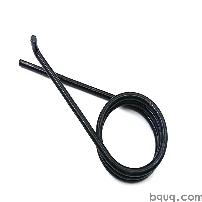
| Torsion spring | Rotational torque | Hinges, levers, lid return, pedal return | Leg geometry and body clearance |
| Extension spring | Pull / axial | Tensioners, retractors, door closers, cable return | Hook stress concentration and initial tension |
Two more considerations cut across all three:
Buckling. A compression spring with a free length more than about 2.6 times its mean diameter can buckle sideways unless guided. Long suspension springs are almost always guided on a damper rod or seated in a pocket for exactly this reason.
Surge and resonance. A spring is a distributed mass-spring system, not a pure spring. At certain frequencies, wave motion travels along the coils and can amplify stress dramatically. If your system has a known excitation frequency — motor RPM, road input, pump pulse — check it against the spring's natural frequency. Our article on spring resonance and surge walks through the calculation.
Material selection for suspension and motion springs
Material choice drives fatigue life, corrosion behaviour, and cost more than any other single decision.
| Material | Shear modulus (N/mm²) | Max service temp | Fatigue | Corrosion | Relative cost |
|---|---|---|---|---|---|
| Music wire (ASTM A228) | 79,000 | ~120 °C | Excellent | Poor | Low |
| Oil-tempered carbon | 79,000 | ~150 °C | Very good | Poor | Low |
| Chrome silicon | 79,000 | ~220 °C | Excellent | Poor | Medium |
| 302 / 304 stainless | 69,000 | ~250 °C | Good | Very good | Medium |
| 17-7PH stainless | 76,000 | ~315 °C | Excellent | Very good | High |
| Phosphor bronze | 43,000 | ~120 °C | Fair | Excellent | Medium |
| Inconel / Hastelloy | 66,000 | 400 °C+ | Excellent | Excellent | Very high |
For suspension work, chrome silicon is the default for high-cycle, high-stress applications because of its fatigue resistance and resistance to sag at elevated temperature. For motion control in wet or washdown environments, 302 or 304 stainless is usually the practical answer. For high-temperature or highly corrosive duty, the nickel alloys come in — see our comparison of Hastelloy and Inconel springs if you are working in that range.
One caution: switching from carbon steel to stainless to "add corrosion resistance" drops G by roughly 13%, which drops rate by the same proportion. You will need to re-tune geometry, not just swap material.
Stress, set, and fatigue
Design stress should sit below the material's allowable for the cycle count you need. As a rough rule for compression springs in dynamic service:
- 10^5 cycles: up to ~45% of tensile strength
- 10^6 cycles: up to ~38% of tensile strength
- 10^7 cycles: up to ~32% of tensile strength
These are indicative percentages used for preliminary sizing, not a substitute for validated fatigue data on your specific geometry and surface condition. Surface quality matters enormously — a scratch or a corrosion pit on a high-stress coil is a crack initiation site. Shot peening, which puts the surface into compression, is one of the cheapest ways to extend fatigue life and is standard practice on automotive suspension springs.
Presetting (scragging) is the other standard step. The spring is compressed past solid height once during manufacture so that the first few cycles of plastic set happen in the factory, not in your assembly. Without it, a suspension spring can lose several millimetres of free length in the first hours of service.
Tolerances, testing, and what to specify on a drawing
Springs are deceptively hard to specify. A drawing that says "compression spring, 250 mm free length" will get you something, but probably not what you need.
Minimum drawing content
- Wire diameter and tolerance
- Outside or inside diameter (state which, and the tolerance)
- Free length and tolerance
- Number of total and active coils
- Rate (N/mm) and the deflection range over which it is measured
- Load at one or two specified lengths — this is the most useful single check
- End condition (closed, closed and ground, open)
- Hand of wind, if relevant
- Material specification and any finish (plating, coating, shot peen)
- Direction of rotation for torsion springs
Inspection points that catch real problems
| Check | Method | Why it matters |
|---|---|---|
| Load at installed length | Load cell at fixed deflection | Catches rate and free length errors together |
| Free length | Optical or contact | Detects set and coiling drift |
| Squareness | Square and feeler gauge | Prevents side loading and buckling |
| Wire diameter | Micrometer | Fourth-power effect on rate |
| Surface condition | Visual at 10× | Crack initiation sites |
| Coil count | Visual / optical | Rate and solid height |
Note that load-at-length testing is far more informative than free length alone. Two springs can share a free length and have different rates, and only a load test reveals it. Length tolerance is worth understanding in detail — our piece on spring length tolerance explains how it interacts with rate tolerance in a stack-up.
Prototype, validate, then scale
The practical sequence for a new suspension or motion spring:
1. Define the two operating points and the cycle life target.
2. Size the geometry using the rate formula, then check solid height and buckling.
3. Pick material based on environment, temperature, and fatigue target.
4. Prototype — short runs are fast and cheap enough to test two or three rate variants side by side. See spring prototype and short-run production.
5. Validate at representative load and cycle count, and measure set after the first 100 cycles.
6. Release with load-at-length as the acceptance criterion, not free length alone.
BQUQ runs four production lines in one Dongguan factory covering CNC machining to ±0.005 mm, metal stamping, custom springs, and heat sinks, so a spring that needs a matching seat, retainer, or heat-treated housing can be sourced together rather than coordinated across three vendors. Flexible MOQ means a 50-piece prototype run and a 50,000-piece production run come from the same process. Quotes go out in 12 working hours.
Frequently Asked Questions
Q: How do I calculate the spring rate I need?
A: Divide the change in load by the change in deflection between your two operating points: k = ΔF/Δx. If the spring must carry 2,400 N at design load and 1,500 N at installed preload over 40 mm of travel, the required rate is 22.5 N/mm. Then size wire diameter, mean diameter, and active coils to hit that rate while respecting solid height and buckling limits.
Q: What is a typical preload for a suspension spring?
A: For vehicle and machine suspension, preload is commonly 15–35% of the total design load, which keeps the spring seated under reversing loads and sets static ride height. Light motion-control springs often run higher preload percentages — 30–50% — because their main job is holding a mechanism in position rather than absorbing large dynamic travel.
Q: Does stainless steel make a good suspension spring?
A: It depends on the environment. Stainless resists corrosion well, but its shear modulus is about 13% lower than carbon steel, so rate drops unless you re-tune geometry. It also has lower fatigue strength than chrome silicon at high stress. Use stainless for wet, washdown, or mildly corrosive duty at moderate stress; use chrome silicon for high-cycle, high-stress suspension work.
Q: Why did my spring lose length after installation?
A: This is set, caused by stress relaxation and local yielding in the first cycles. It is normal in untreated springs and typically amounts to 1–3% of free length. Presetting (scragging) at the factory compresses the spring past solid height once so the set happens before delivery. If set continues beyond the first hundred cycles, your design stress is probably too high.
Q: How many cycles should a suspension spring survive?
A: Automotive suspension springs are typically validated to 10^5–10^6 cycles at representative load, while industrial motion-control springs often target 10^6–10^7. To reach the higher figures, keep design stress under roughly 32–38% of tensile strength, specify shot peening, and control surface finish — pits and scratches are where fatigue cracks start.
Related Resources
- About BQUQ — ISO9001 factory in Dongguan with four production lines under one roof
- Compression springs — suspension, die, and counterbalance spring production
- Torsion springs — lever, hinge, and return-spring design support
- Extension springs — tensioners and retractor springs with custom hooks
- Technical articles — spring design, materials, and tolerance guides
- Industry trends — sourcing and manufacturing shifts in motion components
- Contact — send drawings for a quote in 12 working hours
Authored by the BQUQ Engineering Team. BQUQ (Dongguan) runs CNC machining (±0.005 mm), metal stamping, custom springs, and heat sink production in one ISO9001 factory. Source-direct from Dongguan, China — quote in 12 hours: sc@bquq.com | WhatsApp +86 13713157787 | www.bquq.com


