
Stamped heat sink clips deliver 5-50 N retention without screws. Spring steel, temper and assembly trade-offs from BQUQ, an ISO9001 Dongguan factory.
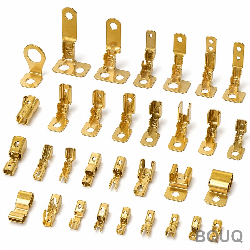
Stamped Heat Sink Clips: Retention Force and Assembly
Short answer: a stamped heat sink clip is engineered to hold a semiconductor, module or LED board against its heatsink with 5–50 N of retention force, and it does that job without a single screw. The standard recipe is spring-tempered 301 or 302 stainless steel in 0.3–0.6 mm thickness, formed so the clip deflects elastically during snap-on assembly and never crosses its yield point. In high volume these clips cost roughly $0.01–$0.10 per piece, which is why screwless clip retention dominates power electronics, LED lighting and DC-DC converter production.
A clip sounds like the simplest part in your BOM, but it is a spring with a job description: keep a fixed force on the component over temperature, vibration and years of service, while still letting an operator or a pick-and-place head install and remove it in seconds. The force number drives thermal performance, because interface material only conducts when it is compressed. Get the clip wrong and a good heatsink runs hot. This guide covers the force targets, the materials, the assembly trade-offs, and the drawing callouts that get a clip made right the first time.
Retention Force: The Number That Drives the Design
Retention force is the load the clip applies to the top of the component once assembled. Too low and the thermal interface gap grows and the part overheats or rattles; too high and the component case can crack, the PCB can bow, or the clip takes a permanent set on the first assembly. Power semiconductor makers commonly publish an acceptable mounting pressure range for each package, and the clip must land inside it at both room temperature and maximum operating temperature.
| Package or application | Typical clip retention force | What sets the target |
|---|---|---|
| TO-220 / TO-220FP | 10–25 N | Datasheet mounting pressure, plastic case strength |
| TO-247 / TO-3P | 20–40 N | Larger case, higher thermal load |
| LED module / board clamp | 5–15 N | Avoid lens damage, keep TIM compressed |
| Power module spring plate | 30–50 N and up | Multiple pressure points, thick baseplate |
These are typical industry working ranges, not a substitute for your datasheet. If the semiconductor manufacturer states a mounting pressure in N/mm², multiply it by the contact area of the component body to get the clip force you need, then add margin for relaxation over life.
One practical rule: measure the force on the component, not the force at the clip tip. A clip that presses at the edge of a TO-247 body applies leverage, so the effective force at the die center is lower than the raw spring force. When you test clips, use a force gauge under the actual component footprint with the actual heatsink, not a bare bench.
What Actually Sets Clip Force: Thickness Cubed, Length Cubed
For a simple cantilever clip the force at a given deflection follows a beam relationship: force scales with thickness cubed and inversely with the cube of the active beam length, linearly with width, and proportionally with the material's elastic modulus. That is why tiny drawing changes make large force changes.
| Parameter change | Effect on clip force | Why |
|---|---|---|
| Thickness +10% | Force up roughly +33% | Force ∝ thickness³ |
| Active beam length +10% | Force down roughly −25% | Force ∝ 1/length³ |
| Width +10% | Force up roughly +10% | Force ∝ width |
| Material change, same geometry | Force changes with modulus | 301 SS vs spring steel vs phosphor bronze |
If your prototype clip measures 20 N and you need 27 N, do not redraw the whole part — a small thickness increase or a shorter beam gets you there. Conversely, if assembly is too stiff, lengthening the beam a little softens it fast. This scaling is why the same die family can cover a range of forces by changing strip thickness alone, and why progressive die tooling for clips is usually designed with thickness variants in mind.
Keep in mind that the force at the drawing's nominal dimension is not the force you get. Sheet thickness tolerance, temper variation and bend springback all shift the result, typically ±10% or more across a coil. If the application is sensitive, design the clip to land mid-range of the datasheet window so the spread does not push you out of it. Good stamping process control and incoming coil verification keep that spread tight in production.
Clip Materials Compared
Material choice is a balance of service temperature, corrosion, cost and formability. The clip must survive the forming bend without cracking and keep its temper after stamping — many clips are stamped from pre-hardened strip and are never heat treated afterwards.
| Material | Typical thickness | Useful temperature ceiling | Notes |
|---|---|---|---|
| 301/302 stainless, full hard | 0.2–0.6 mm | ~250–300 °C continuous | Standard choice; corrosion resistant, needs no plating |
| 65Mn / C75S spring steel (SAE 1075 class) | 0.3–1.0 mm | ~150–200 °C | Cheaper, high force, must be plated or oiled against rust |
| 17-7PH stainless (conditioned) | 0.2–0.5 mm | ~300 °C+ | Higher temperature and relaxation resistance, pricier |
| Beryllium copper / phosphor bronze | 0.1–0.4 mm | ~150 °C | Non-magnetic, conductive, for small signal clips |
Austenitic stainless in the fully hardened condition is the workhorse because it resists corrosion without plating, so there is no coating to wear or chip at the contact point, and no hydrogen embrittlement risk from an acid plating bath. Spring steel gives more force per millimeter of thickness and costs less, but it rusts, so it needs zinc or nickel plating, and plated clips demand a stress-relief bake to avoid hydrogen embrittlement.
Watch the galvanic couple: a stainless clip pressed against an aluminum heatsink in a humid environment can corrode the aluminum at the contact line. In practice most clip designs add a small plastic pad, an anodized heatsink surface, or a dab of conformal coating at the contact point. If you are pairing clips with extruded or stamped aluminum heatsinks, ask your supplier how they handle that interface on existing products.
How Assembly Method Shapes the Clip
Clip assembly is a deflection event. To snap over a component the clip must deflect past its service position, and if that assembly deflection exceeds the elastic limit the clip takes a set and retention force drops immediately. Three consequences follow. First, the assembly deflection — not the service deflection — is the number to check against yield. Second, a clip that is easy to install by hand is often near its yield limit, so force and installability pull in opposite directions. Third, the clip needs an intentional release feature: a pry tab, a hole for a tool, or a shaped finger, or the field service technician will destroy the component getting it off.
| Assembly approach | Typical installed clip force | Rework | Automation fit |
|---|---|---|---|
| Hand snap with pry tab | 5–25 N | Easy, tool-free | Manual stations |
| Press-fit with tooling head | 20–50 N | Needs pry tool | High-volume auto lines |
| Screwless push-pin clip | 10–30 N per pin | Moderate | Very good with auto drivers |
| Screw + spring washer (alternative) | Torque-controlled | Very easy | Slower, higher part count |
Assembly speed is where clips win. A screw joint needs a driver, torque control and a thread — call it several seconds of labor plus fastener cost. A clip snaps in one motion. In LED troffers, automotive electronics and consumer power supplies, that saving pays for the tooling quickly. If your clip is for a product that is never serviced, you can bias the design toward a stiffer press-fit; if it sits behind a service door, keep the release feature and keep the force at the lower end so a technician can handle it.
Stress Relaxation: The Force That Quietly Leaks Away
Every clip loses a little force over time because stressed metal relaxes, and the rate climbs steeply with temperature. A stainless clip that starts at 25 N can sit at 18–20 N after thousands of hours at 120 °C, depending on stress level and material. The failure mode is not dramatic — the clip does not break, the interface just slowly opens and the component runs hotter until something derates or dies.
Designers counter relaxation three ways: run the clip at a lower fraction of yield stress, choose a more relaxation-resistant material such as 17-7PH or a precipitation-hardened grade for hot applications, and add a pre-load or over-bend during forming so the clip still carries the target force after settling. Testing should include a thermal soak: assemble clips on a test heatsink, load the assembly at the maximum rated temperature for several hundred hours, and re-measure retention force. If force stays within spec, the design is safe; if it drifts, change the material before you change the thickness.
Getting Your Clip Quoted and Made
When you send a clip drawing, add three things a stamper needs but buyers often omit: the required retention force range and where to measure it, the assembly deflection and any installation tool limit, and the service temperature profile. With those, a source factory can select strip thickness and temper, simulate the forming and springback, and build the die so the formed part lands mid-tolerance. Precision metal stamping suppliers in Dongguan typically quote clips at stamping tolerances of ±0.05 mm on formed features, with prototype tooling in weeks and progressive die costs amortized across the quantity you actually need. Send the drawing and the force spec together — the force spec is what separates a clip that works from a clip that just looks like one.
Frequently Asked Questions
Q: What retention force do heat sink clips need?
A: Most power semiconductor packages work with 5–50 N of clip force: roughly 10–25 N for TO-220, 20–40 N for TO-247, and more for large power module baseplates. Check the component datasheet's mounting pressure spec, multiply by the contact area, and add margin for relaxation, because datasheet minimums assume fresh clips.
Q: What is the best material for a stamped heat sink clip?
A: Spring-tempered 301 or 302 stainless in 0.3–0.6 mm thickness is the standard answer: it resists corrosion without plating, keeps its temper through forming, and handles typical electronics temperatures. Use 17-7PH or a similar precipitation-hardened grade above roughly 250–300 °C, and use plated spring steel only when cost pressure is severe and corrosion protection is managed.
Q: How much do stamped heat sink clips cost?
A: In high volume a stamped stainless clip typically runs $0.01–$0.10 per piece before plating or pads. What you really pay for is the die: simple clip tooling typically starts in the low thousands of dollars, and the unit price depends on strip thickness, material, and whether secondary forming operations are needed.
Q: Why does my clip lose force after months in service?
A: That is stress relaxation, not a manufacturing fault. Stressed metal slowly relaxes and the rate increases with temperature, so retention force drifts down over time. Counter it by keeping working stress well below yield, choosing a relaxation-resistant material for hot spots, and verifying the design with a thermal soak test before production release.
Q: What should I put on the drawing besides dimensions?
A: State the required retention force range and the measurement point, the assembly deflection or installation force limit, and the maximum service temperature. Add material grade, temper, and thickness tolerance. A stamper who knows the force target can select strip and design the die correctly; a drawing with only dimensions leaves those decisions to guesswork.
Related Resources
- Heat sink mounting methods compared — clips, screws, springs and adhesives on the same thermal budget.
- Precision metal stamping services — progressive die stamping of clips, terminals and brackets in Dongguan.
- About BQUQ — an ISO9001-certified source factory running stamping, CNC, spring and heat sink lines under one roof.
- Contact us — send the clip drawing and force spec for a quote within 12 working hours.
Authored by the BQUQ Engineering Team. BQUQ is an ISO9001-certified source factory in Dongguan, China, running CNC machining, metal stamping, custom springs, heat sink and collet lines under one roof. Send drawings to sc@bquq.com or WhatsApp +86 13713157787 for a quote within 12 working hours. www.bquq.com


