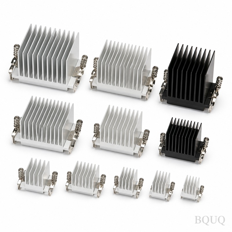
heat sink for ssd: 1050A aluminium, 0.4 mm fins at 3.0 mm pitch, 0.10 mm over 100 mm flatness, 0.48 K/W thermal resistance. MOQ 200 pcs, ships in 5 working d...
heat sink for ssd
heat sink for ssd: 1050A aluminium, 0.4 mm fins at 3.0 mm pitch, 0.10 mm over 100 mm flatness, 0.48 K/W thermal resistance. MOQ 200 pcs, ships in 5 working d...
Get a Fast Quote for This Part
Send us your drawing / quantity / material — reply within 24h.
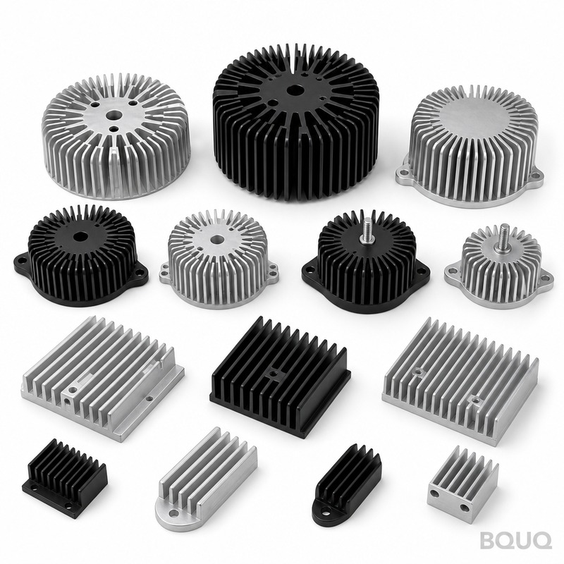
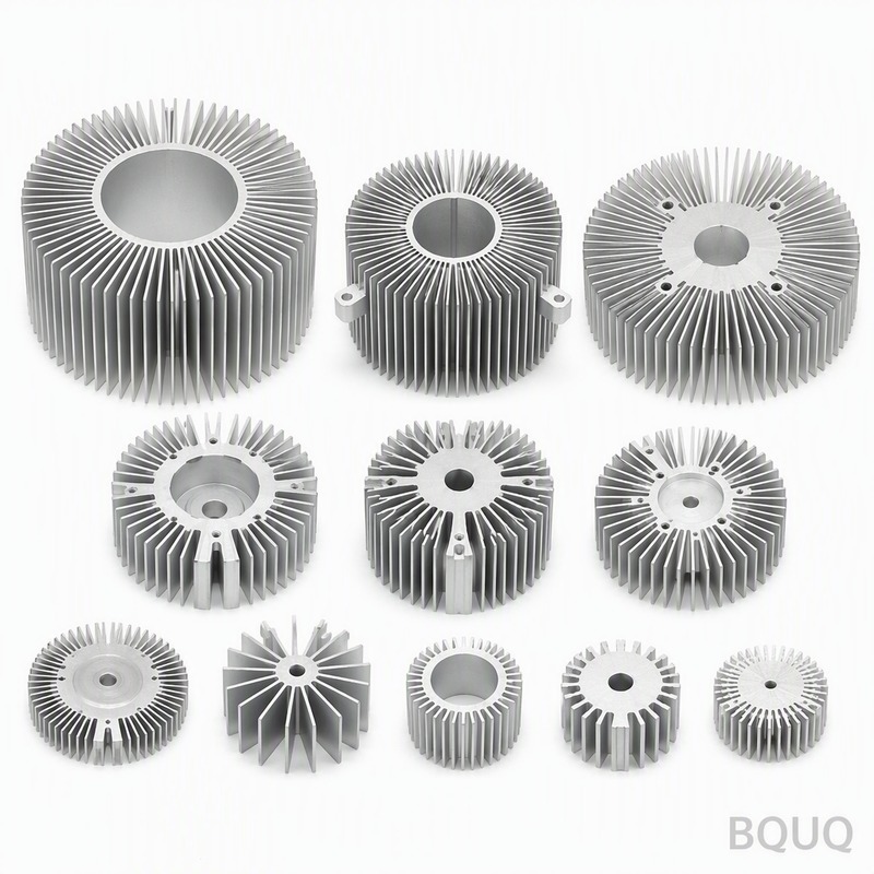
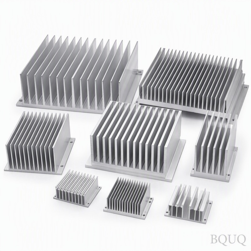
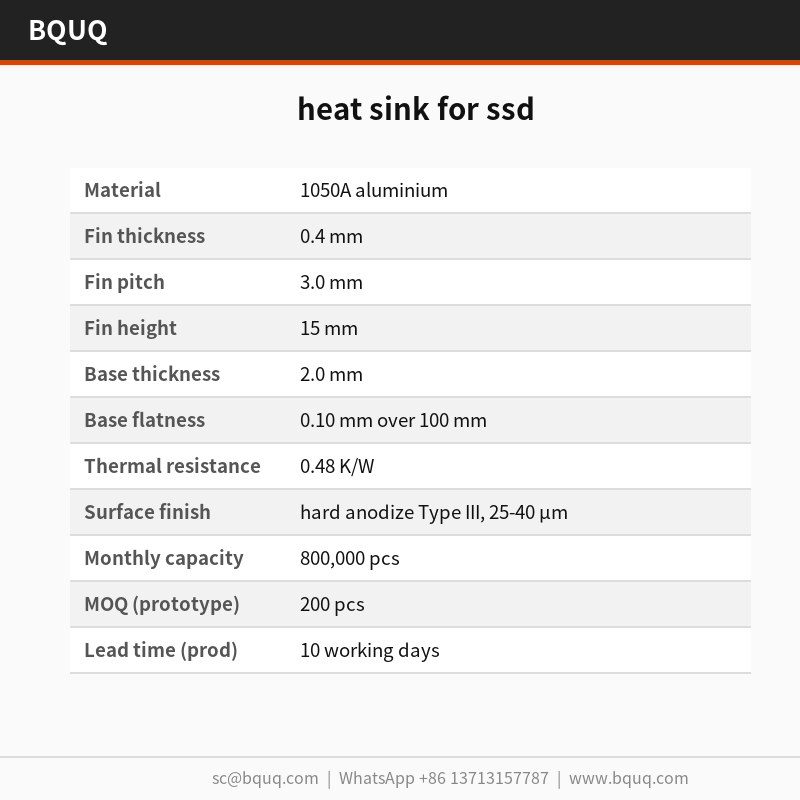
A heat sink for SSD is stamped from 1050A aluminium with a 2.0 mm base and 0.4 mm fins at 3.0 mm pitch. It holds 0.10 mm over 100 mm and delivers 0.48 K/W at ΔT = 75 K with forced air at 2.0 m/s. Monthly capacity reaches 800,000 pcs, with Type III hard anodize at 25-40 µm.
A 2.0 mm base and 0.4 mm fins define this heat sink for ssd. Pressed from 1050A aluminium on 110 T tooling, it holds 0.10 mm over 100 mm and returns 0.48 K/W at ΔT = 75 K, forced air 2.0 m/s. Monthly output runs at 800,000 pcs.
Design Approach and Process
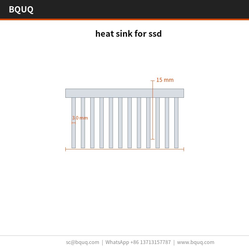
Low fin gauge is where stamping wins: 0.4 mm fins at 3.0 mm pitch give more surface per cubic millimetre than a machined or extruded profile of the same envelope.
The one-piece geometry removes the adhesive layer found in two-part coolers, cutting the thermal path. Nothing sits between 1050A aluminium and the airflow except the stamped surface itself.
Stamped construction tolerates batch variation better than extrusion: die wear shows up first as a measurable shift in fin pitch, which inspection catches at CMM 0.001 mm resolution rather than in the field.
Every stroke is dimensionally identical, so ±0.15 mm hole position carries across the batch. That is what makes LED high bay lighting volume programs repeatable.
The hard anodize Type III, 25-40 µm finish is applied after forming, so corrosion protection does not get cut through at the fin roots the way it does on machined alternatives.
Material Selection and Surface Finish
The standard material is 1050A aluminium, supplied with hard anodize Type III, 25-40 µm. For applications where LED high bay lighting exposure is a concern, we recommend the passivated route; where conductivity matters more than weight, copper C110 raises thermal performance and roughly doubles unit mass.
Tolerance Classes You Can Specify
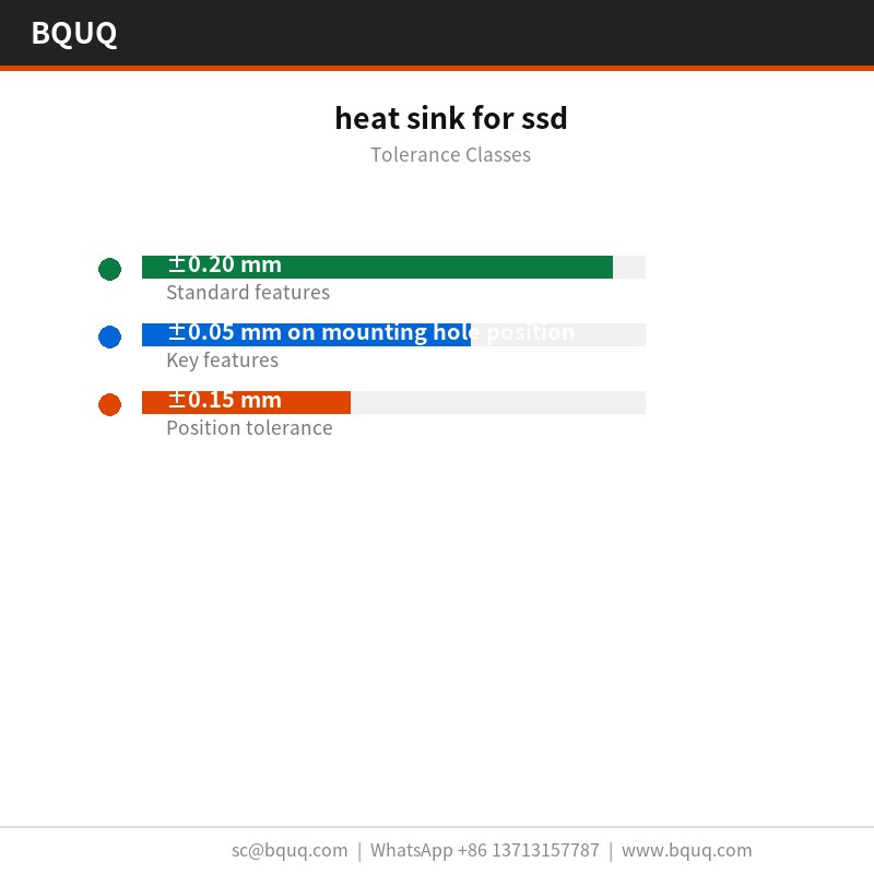
General dimensions run to ±0.20 mm, with critical features such as ±0.05 mm on mounting hole position held separately. Formed geometry inherits tooling repeatability of ±0.03 mm, and hole position is held to ±0.15 mm. Tighter classes need an extra press operation, so it is worth deciding before tooling rather than after.
Flatness is checked on a granite surface plate, 25 °C against a 0.10 mm over 100 mm limit, and fin pitch is verified optically at ±0.03 mm. Reports go out with each lot.
Lot traceability runs from coil to carton: heat number, press stroke range and inspection record stay attached, so a field issue can be tied back to a specific run.
We inspect 0.4 mm fin tips for burr and crack after forming, because stamping can split a root without shifting any drawing dimension. Burr limit is set per part.
Final containment is Anti-static bag + wooden crate over 50 kg. Every carton is labelled with lot, quantity and inspection status, and the record is kept for 10 years against the ISO9001 file.
Where This Part Is Used
In LED high bay lighting, the 0.48 K/W rating determines how much airflow the enclosure still needs. At LED high bay lighting junction temperatures, 0.4 mm fins at 3.0 mm pitch keep the delta-T inside the sensor budget.
LED high bay lighting programs are the reason this geometry exists. Where the enclosure cannot grow taller, fin density is the only lever, and 3.0 mm pitch with 0.4 mm stock is the practical ceiling for aluminium.
LED high bay lighting packaging and vibration rules push toward one-piece construction. A stamped heat sink for ssd has no adhesive to creep, which is the usual failure mode in two-part coolers.
Designers working on LED high bay lighting ask for flatness before they ask for thermal data, because LED high bay lighting assembly is automated and a non-flat base stops the line.
Prototype is 5 working days from drawing approval; production is 10 working days after the first article is signed off. Tooling for a new part takes . We quote FOB Guangzhou, and sea freight to Europe runs about 25 to 30 days after booking.
How does this compare to an extruded heat sink for ssd?
Extrusion is cheaper above roughly 500,000 pieces per year and gives a smoother profile. Stamping wins below that and wherever fin gauge drops below 0.5 mm, because extrusion cannot hold 0.4 mm consistently. For LED high bay lighting prototypes, tooling cost usually decides it.
We test at ΔT = 75 K, forced air 2.0 m/s and report 0.48 K/W. That is a steady-state figure, not a transient: for LED high bay lighting first-power-on behaviour you need a different test, and we can run it on request.
Can you deliver without surface treatment?
Yes, we ship as-pressed for customers who do their own finishing. The risk is handling marks on 0.4 mm fins, so we pack those parts with interleaving sheets inside Anti-static bag + wooden crate over 50 kg.
Do you provide CAD files or a drawing?
We supply a 2D drawing with the CMM report, and 3D STEP on request. Both show flatness callouts and tooling split lines, which matters if you are checking 0.10 mm over 100 mm in your own assembly.
How We Manufacture and Ship
The line sits in Dongguan in a single ISO9001 plant. 110 T presses cover the heat sink for ssd family, and 800,000 pcs per month is current committed output.
Our LED high bay lighting experience runs back to the first tooling programme in 2015. That history is why the standard hard anodize Type III, 25-40 µm and ±0.20 mm are conservative rather than optimistic.
±0.15 mm hole position; 0.10 mm over 100 mm flatness
Lead time
Standard for stamped tooling programs; confirm with BQUQ
MOQ
Volume production; confirm with BQUQ
Capacity
800,000 pcs per month
Selection / comparison
Option
Best for
Trade-off
Stamped 1050A aluminium
High-volume SSD cooling with 0.4 mm fins
Requires tooling; fin pitch shifts with die wear
Extruded profile
Lower tooling cost for simple shapes
Lower surface density; batch variation from extrusion
Machined heat sink
Prototype or low-volume custom geometry
Higher cost per part; adhesive layer in two-part coolers adds thermal path
Two-part cooler with adhesive
Applications needing separate base and fin stack
Adhesive layer increases thermal resistance
Stamped with Type III hard anodize
Corrosion protection after forming
Anodize adds process step; 25-40 µm thickness
Process / inspection
Stage
Control
Record
Stamping
110 T tooling; 0.4 mm fins at 3.0 mm pitch
Stroke dimensions; fin pitch
Forming
One-piece geometry; no adhesive layer
Base 2.0 mm; fin height as specified
Anodizing
Type III hard anodize, 25-40 µm after forming
Coating thickness; corrosion protection at fin roots
Inspection
CMM 0.001 mm resolution; 0.10 mm over 100 mm
Flatness; hole position ±0.15 mm
Final
Inspection before every shipment
Batch dimensional report
Frequently Asked Questions
What is the thermal resistance of this heat sink for SSD?
It returns 0.48 K/W at ΔT = 75 K with forced air at 2.0 m/s. The 2.0 mm base and 0.4 mm fins at 3.0 mm pitch provide high surface area per cubic millimetre, and the one-piece stamped geometry removes the adhesive layer found in two-part coolers.
The heat sink is pressed from 1050A aluminium. After forming, it receives Type III hard anodize at 25-40 µm. This protects corrosion without cutting through at the fin roots, unlike machined alternatives where anodize can be compromised.
What tolerances can I expect on the stamped heat sink?
Flatness holds 0.10 mm over 100 mm. Hole position carries ±0.15 mm across the batch because every stroke is dimensionally identical. Inspection uses CMM at 0.001 mm resolution to catch die wear as a shift in fin pitch.
What is the monthly production capacity?
Monthly output runs at 800,000 pcs. The 110 T tooling and 0.4 mm fins at 3.0 mm pitch support repeatable high-volume programs. This capacity suits LED high bay lighting and similar volume applications.
Why choose stamped construction over extrusion or machining?
Stamping wins on fin gauge: 0.4 mm fins at 3.0 mm pitch give more surface per cubic millimetre than machined or extruded profiles in the same envelope. The one-piece geometry removes the adhesive layer, cutting the thermal path. Stamped construction also tolerates batch variation better.
How is quality controlled before shipment?
Inspection before every shipment uses CMM at 0.001 mm resolution. Die wear shows first as a measurable shift in fin pitch, which is caught before field issues. Flatness is verified to 0.10 mm over 100 mm, and hole position to ±0.15 mm.
It is used in SSD cooling and similar electronics. The stamped 1050A aluminium design with Type III hard anodize suits volume programs such as LED high bay lighting, where repeatable ±0.15 mm hole position and 800,000 pcs monthly output matter.