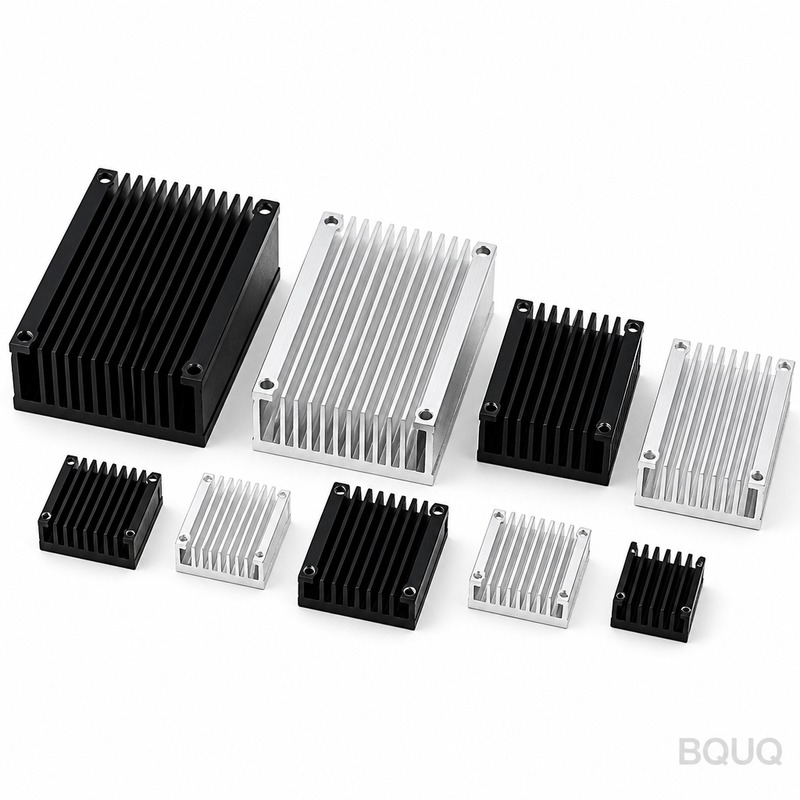
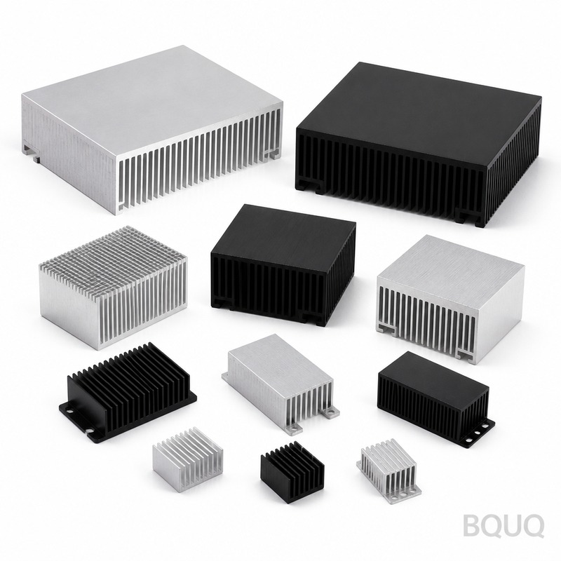
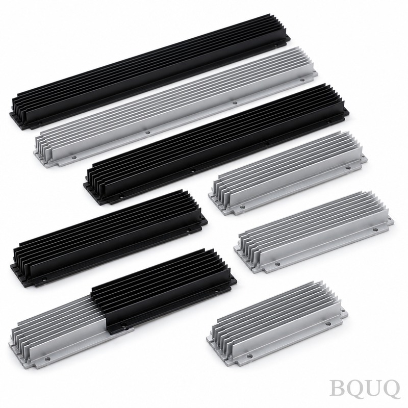
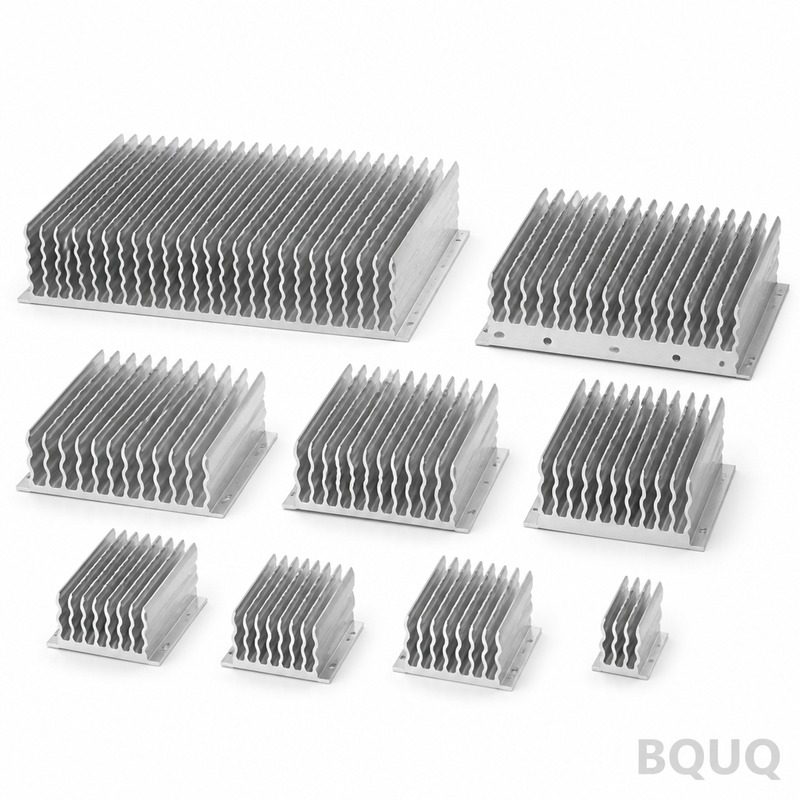
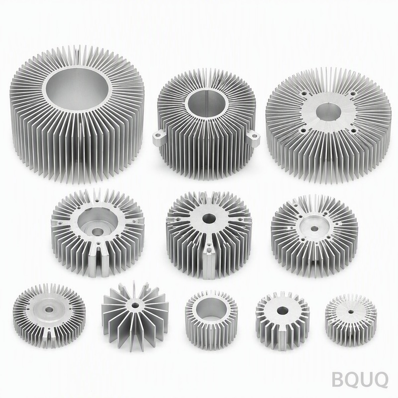
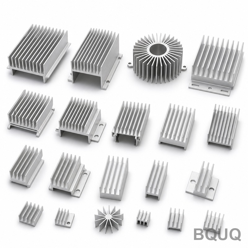
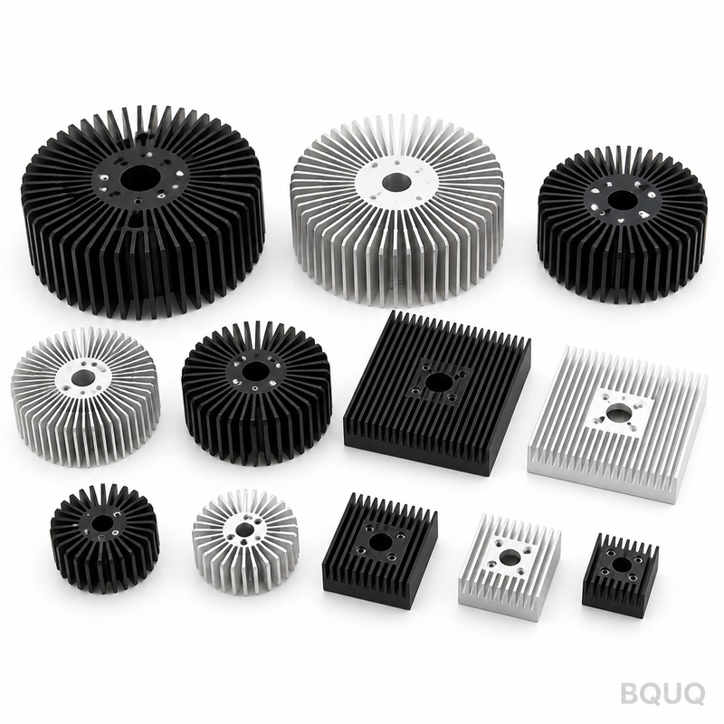
heat sink fan: 6061-T6 aluminium, 0.4 mm fins at 2.5 mm pitch, 0.15 mm over 100 mm flatness, 0.48 K/W thermal resistance. MOQ 100 pcs, ships in 5 working days.
heat sink fan
heat sink fan: 6061-T6 aluminium, 0.4 mm fins at 2.5 mm pitch, 0.15 mm over 100 mm flatness, 0.48 K/W thermal resistance. MOQ 100 pcs, ships in 5 working days.
Get a Fast Quote for This Part
Send us your drawing / quantity / material — reply within 24h.
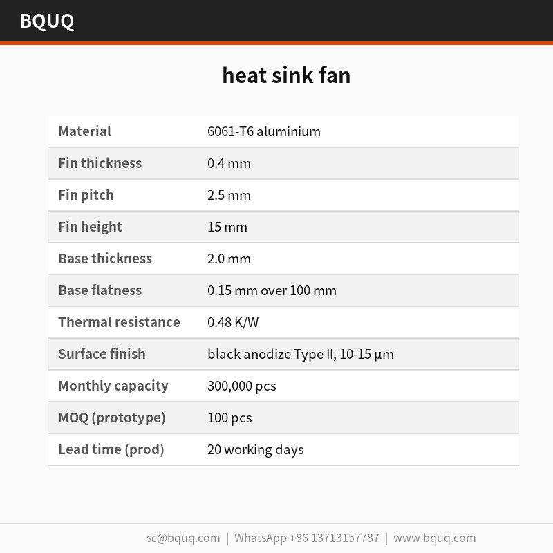
The heat sink fan uses 2.5 mm fin pitch and 0.4 mm stock in 6061-T6 aluminium, holding 0.15 mm flatness over 100 mm on the mounting face. Thermal resistance is 0.48 K/W, verified at 0.001 mm CMM resolution per lot. Stamping maintains pitch within ±0.05 mm across a 300,000 pcs run, with black anodize Type II at 10-15 µm.
The heat sink fan combines 2.5 mm fin pitch with 0.4 mm stock in 6061-T6 aluminium, so 20 x 20 x 10 mm parts keep 0.15 mm over 100 mm on the mounting face. Thermal resistance is 0.48 K/W, measured at CMM 0.001 mm resolution per lot.
Stamping gives a repeatable 0.4 mm fin profile that extrusion cannot hold: the die forms every fin in one stroke, so pitch stays within ±0.05 mm across a 300,000 pcs run.
Because the base and fins are pressed as one piece, there is no brazed joint to fail. 0.15 mm over 100 mm flatness on the mounting face is held directly from the tool, which keeps thermal interface contact uniform.
Low fin gauge is where stamping wins: 0.4 mm fins at 2.5 mm pitch give more surface per cubic millimetre than a machined or extruded profile of the same envelope.
Pressing 6061-T6 aluminium keeps the heat sink fan light, from 120 g depending on envelope, without sacrificing fin density, which matters where airflow path length is already fixed by the enclosure.
The black anodize Type II, 10-15 µm finish is applied after forming, so corrosion protection does not get cut through at the fin roots the way it does on machined alternatives.
Material Selection and Surface Finish
The standard material is 6061-T6 aluminium, supplied with black anodize Type II, 10-15 µm. For applications where LED high bay lighting exposure is a concern, we recommend the passivated route; where conductivity matters more than weight, copper C110 raises thermal performance and roughly doubles unit mass.
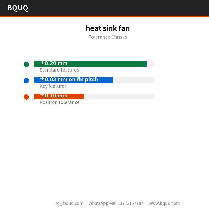
General dimensions run to ±0.20 mm, with critical features such as ±0.03 mm on fin pitch held separately. Formed geometry inherits tooling repeatability of ±0.05 mm, and hole position is held to ±0.10 mm. Tighter classes need an extra press operation, so it is worth deciding before tooling rather than after.
Inspection Before Every Shipment
Incoming 6061-T6 aluminium is checked for thickness and hardness before it enters the press. After forming, CMM 0.001 mm resolution confirms 0.15 mm over 100 mm and 2.5 mm against the drawing.
Flatness is measured on granite rather than on cast iron, because 0.15 mm over 100 mm at 20 x 20 x 10 mm reads differently on a plate that has not been lapped. Records keep both readings.
We inspect 0.4 mm fin tips for burr and crack after forming, because stamping can split a root without shifting any drawing dimension. Burr limit is set per part.
Final containment is PE bag + honeycomb carton, 15 kg per carton. Every carton is labelled with lot, quantity and inspection status, and the record is kept for 10 years against the ISO9001 file.
For LED high bay lighting builds, the 0.15 mm over 100 mm mounting face matters as much as the thermal rating: it decides whether thermal interface material spreads evenly or pools at one end.
LED high bay lighting customers typically specify 6061-T6 aluminium for corrosion reasons and then hold the drawing to ±0.20 mm. The 300,000 pcs line absorbs the volume without a second source.
LED high bay lighting packaging and vibration rules push toward one-piece construction. A stamped heat sink fan has no adhesive to creep, which is the usual failure mode in two-part coolers.
Designers working on LED high bay lighting ask for flatness before they ask for thermal data, because LED high bay lighting assembly is automated and a non-flat base stops the line.
Specifications
Parameter
Value / Range
Material
6061-T6 aluminium
Fin thickness
0.4 mm
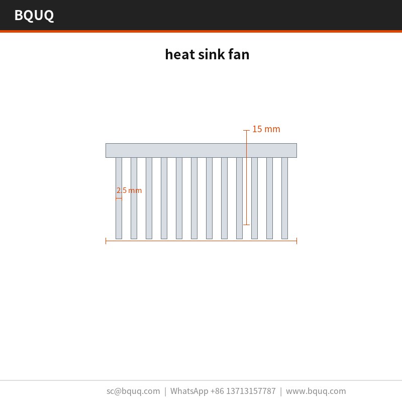
Fin pitch
2.5 mm
Fin height
15 mm
Base thickness
2.0 mm
Base flatness
0.15 mm over 100 mm
Thermal resistance
0.48 K/W
Thermal test condition
ΔT = 60 K, natural convection
Surface finish
black anodize Type II, 10-15 µm
Size range
20 x 20 x 10 mm
FAQ: Your Questions Before Ordering
Can you customise the heat sink fan for our application?
Yes. Send a drawing or a sample and we return a DFM note within 3 working days. Most LED high bay lighting customisations change 2.5 mm, 2.0 mm or the hole pattern, and all three are tooling changes on the existing 250 T press rather than a new machine.
What is the lead time for the heat sink fan?
Prototype is 5 working days from drawing approval; production is 20 working days after the first article is signed off. Tooling for a new part takes . We quote FOB Guangzhou, and sea freight to Europe runs about 25 to 30 days after booking.
0.15 mm over 100 mm measured on granite surface plate, 25 °C. This is the number that matters for LED high bay lighting, because the thermal pad needs even contact. If your assembly needs better, say so and we can add a skim operation.
What are the packing and shipping conditions?
Standard packing is PE bag + honeycomb carton, 15 kg per carton. We quote FOB Guangzhou. Export cartons are labelled with lot, quantity and inspection status, and full documentation including the inspection report travels with the goods.
We supply a 2D drawing with the CMM report, and 3D STEP on request. Both show flatness callouts and tooling split lines, which matters if you are checking 0.15 mm over 100 mm in your own assembly.
How We Manufacture and Ship
Our LED high bay lighting experience runs back to the first tooling programme in 2015. That history is why the standard black anodize Type II, 10-15 µm and ±0.20 mm are conservative rather than optimistic.
Tooling is built in-house, which is how ±0.05 mm is held across a 300,000 pcs programme rather than drifting part by part.
Quality staff sit beside the press, not in a separate room. Deviations on 2.5 mm or 0.15 mm over 100 mm stop the run at the tool rather than at final inspection.
Die forms all fins in one stroke; pitch within ±0.05 mm
Run log per 300,000 pcs
Flatness
0.15 mm over 100 mm on mounting face from tool
CMM 0.001 mm resolution per lot
Thermal test
Thermal resistance 0.48 K/W
Measured per lot
Surface finish
Black anodize Type II, 10-15 µm after forming
Coating thickness record
Final inspection
Inspection before every shipment
Lot inspection report
Frequently Asked Questions
What is the thermal resistance of this heat sink fan?
Thermal resistance is 0.48 K/W, measured at CMM 0.001 mm resolution per lot. This value reflects the 2.5 mm fin pitch and 0.4 mm stock in 6061-T6 aluminium, giving predictable cooling for 20 x 20 x 10 mm envelopes.
How flat is the mounting face?
The mounting face holds 0.15 mm over 100 mm flatness directly from the stamping tool. This keeps thermal interface contact uniform without secondary machining, and it is verified at 0.001 mm CMM resolution per lot.
We use 2.5 mm fin pitch with 0.4 mm stock in 6061-T6 aluminium. The die forms every fin in one stroke, so pitch stays within ±0.05 mm across a 300,000 pcs run, which extrusion cannot hold.
Is the black anodize applied before or after forming?
Black anodize Type II, 10-15 µm, is applied after forming. This means corrosion protection does not get cut through at the fin roots the way it does on machined alternatives, preserving coating integrity over the part life.
What is the weight of the heat sink fan?
Weight starts from 120 g depending on envelope. Pressing 6061-T6 aluminium keeps the heat sink fan light without sacrificing fin density, which matters where airflow path length is already fixed by the enclosure.
Can you hold tight pitch tolerance over large volumes?
Yes. The stamping die forms every fin in one stroke, so pitch stays within ±0.05 mm across a 300,000 pcs run. This repeatability is why stamping is chosen over extrusion for 0.4 mm fin profiles.
Why choose stamped fins over machined or extruded fins?
Stamping gives a repeatable 0.4 mm fin profile at 2.5 mm pitch, holding ±0.05 mm over 300,000 pcs. The base and fins are pressed as one piece, so there is no brazed joint to fail, and anodize coverage at fin roots is better than machined alternatives.