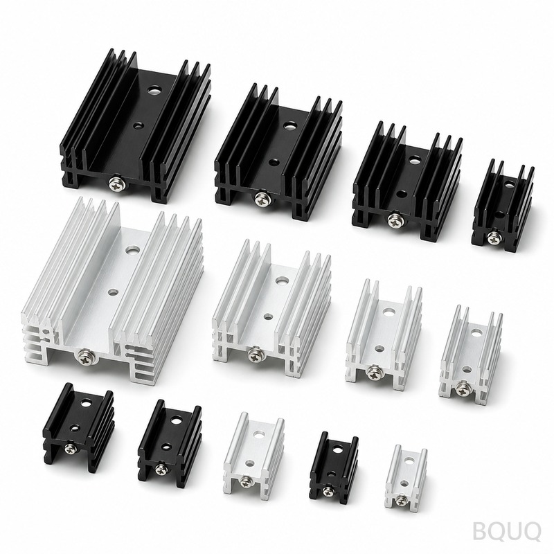
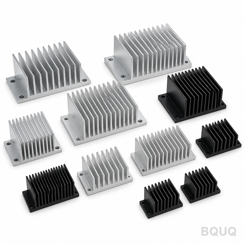
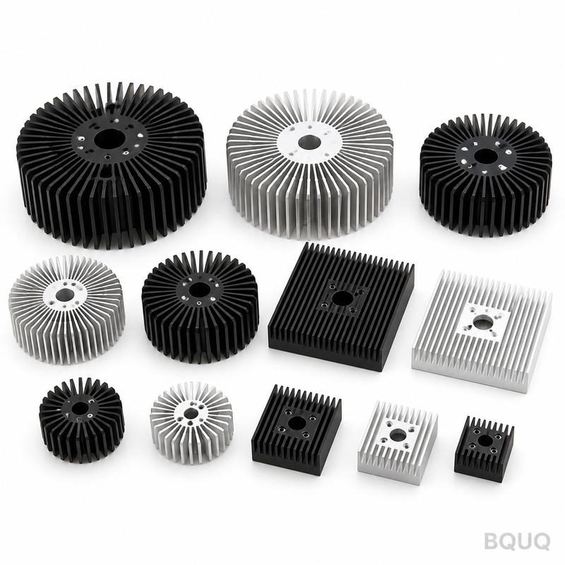
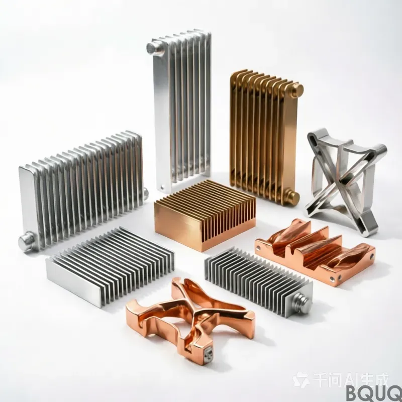
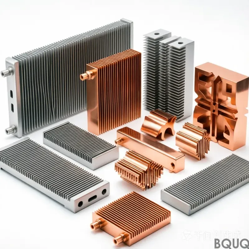
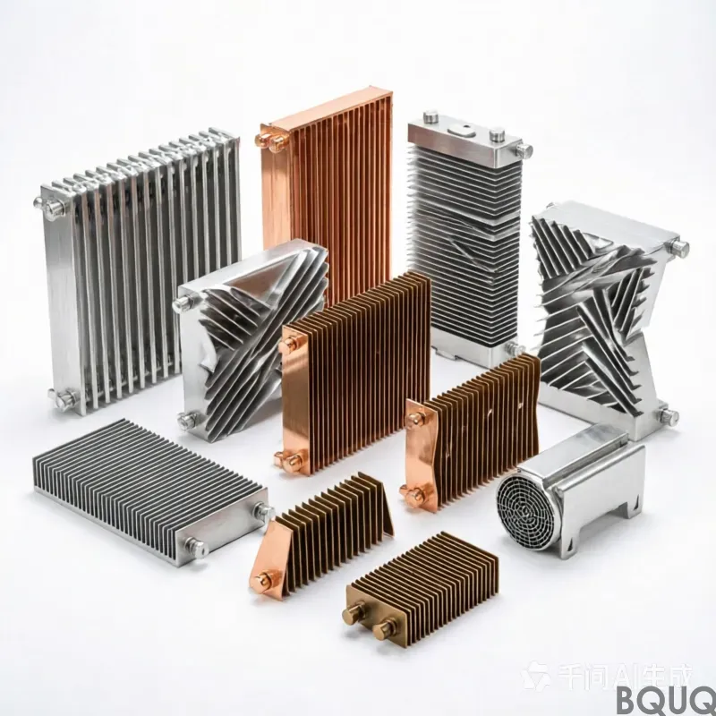
aluminum heat sinks: 6063-T5 aluminium, 0.5 mm fins at 1.5 mm pitch, 0.10 mm over 100 mm flatness, 0.62 K/W thermal resistance. MOQ 50 pcs, ships in 7 workin...
aluminum heat sinks
aluminum heat sinks: 6063-T5 aluminium, 0.5 mm fins at 1.5 mm pitch, 0.10 mm over 100 mm flatness, 0.62 K/W thermal resistance. MOQ 50 pcs, ships in 7 workin...
Get a Fast Quote for This Part
Send us your drawing / quantity / material — reply within 24h.
Aluminum heat sinks in 6063-T5 aluminium deliver 0.62 K/W thermal resistance under ΔT = 75 K with forced air at 2.0 m/s. Stamped fins are 0.5 mm thick at 1.5 mm pitch over a 3.0 mm base, holding pitch within ±0.05 mm across a 120,000 pcs run. Parts start from 15 g, with Type III hard anodize at 25-40 µm. Every batch ships with a CMM report and 100% hydraulic press leak test.
Aluminum heat sinks in 6063-T5 aluminium deliver 0.62 K/W thermal resistance under ΔT = 75 K with forced air at 2.0 m/s. Stamped fins are 0.5 mm thick at 1.5 mm pitch over a 3.0 mm base, holding pitch within ±0.05 mm across a 120,000 pcs run. Parts start from 15 g, with Type III hard anodize at 25-40 µm.
A aluminum heat sinks in 6063-T5 aluminium delivers 0.62 K/W thermal resistance under ΔT = 75 K, forced air 2.0 m/s. Fins are 0.5 mm thick at 1.5 mm pitch over a 3.0 mm base, and every batch ships with a CMM report at CMM plus 100% hydraulic press leak test.
Design Approach and Process
Stamping gives a repeatable 0.5 mm fin profile that extrusion cannot hold: the die forms every fin in one stroke, so pitch stays within ±0.05 mm across a 120,000 pcs run.
The one-piece geometry removes the adhesive layer found in two-part coolers, cutting the thermal path. Nothing sits between 6063-T5 aluminium and the airflow except the stamped surface itself.
Stamped construction tolerates batch variation better than extrusion: die wear shows up first as a measurable shift in fin pitch, which inspection catches at CMM plus 100% hydraulic press leak test rather than in the field.
Pressing 6063-T5 aluminium keeps the aluminum heat sinks light, from 15 g depending on envelope, without sacrificing fin density, which matters where airflow path length is already fixed by the enclosure.
The hard anodize Type III, 25-40 µm finish is applied after forming, so corrosion protection does not get cut through at the fin roots the way it does on machined alternatives.
Material Selection and Surface Finish
The standard material is 6063-T5 aluminium, supplied with hard anodize Type III, 25-40 µm. For applications where switch-mode power supply exposure is a concern, we recommend the passivated route; where conductivity matters more than weight, copper C110 raises thermal performance and roughly doubles unit mass.
Tolerance Classes You Can Specify
General dimensions run to ±0.20 mm, with critical features such as ±0.05 mm on base thickness held separately. Formed geometry inherits tooling repeatability of ±0.05 mm, and hole position is held to ±0.10 mm. Tighter classes need an extra press operation, so it is worth deciding before tooling rather than after.
Inspection Before Every Shipment
Flatness is checked on a granite surface plate, 20 °C against a 0.10 mm over 100 mm limit, and fin pitch is verified optically at ±0.05 mm. Reports go out with each lot.
Sampling is AQL 0.65 for critical dimensions and 1.5 for general, with CMM plus 100% hydraulic press leak test on every first article. Deviations beyond ±0.20 mm trigger a full-lot sort.
We inspect 0.5 mm fin tips for burr and crack after forming, because stamping can split a root without shifting any drawing dimension. Burr limit is set per part.
Final containment is PE bag + honeycomb carton, 15 kg per carton. Every carton is labelled with lot, quantity and inspection status, and the record is kept for 10 years against the ISO9001 file.
Where This Part Is Used
In switch-mode power supply, the 0.62 K/W rating determines how much airflow the enclosure still needs. At switch-mode power supply junction temperatures, 0.5 mm fins at 1.5 mm pitch keep the delta-T inside the sensor budget.
Where a aluminum heat sinks runs at switch-mode power supply volumes, part-to-part consistency decides field returns. ±0.05 mm on a 120,000 pcs run keeps the thermal curve inside one band.
In switch-mode power supply, the base usually doubles as the mounting interface. 3.0 mm with 0.10 mm over 100 mm flat gives a stable surface for the switch-mode power supply thermal pad.
switch-mode power supply designs often run a 2.0 m/s forced-air path. 0.62 K/W at ΔT = 75 K, forced air 2.0 m/s means switch-mode power supply can hold its target with fan power below the acoustic limit.
Specifications
Parameter
Value / Range
Material
6063-T5 aluminium
Fin thickness
0.5 mm
Fin pitch
1.5 mm
Fin height
35 mm
Base thickness
3.0 mm
Base flatness
0.10 mm over 100 mm
Thermal resistance
0.62 K/W
Thermal test condition
ΔT = 75 K, forced air 2.0 m/s
Surface finish
hard anodize Type III, 25-40 µm
Size range
80 x 60 x 35 mm
FAQ: Your Questions Before Ordering
Can you customise the aluminum heat sinks for our application?
Yes. Send a drawing or a sample and we return a DFM note within 3 working days. Most switch-mode power supply customisations change 1.5 mm, 3.0 mm or the hole pattern, and all three are tooling changes on the existing 25 T press rather than a new machine.
Every lot is inspected with CMM plus 100% hydraulic press leak test, and the report is included in the shipment. We check 0.10 mm over 100 mm, 1.5 mm, 3.0 mm and hole position against ±0.20 mm. Lot traceability from coil to carton is kept for 10 years.
Do you test for thermal resistance?
We test at ΔT = 75 K, forced air 2.0 m/s and report 0.62 K/W. That is a steady-state figure, not a transient: for switch-mode power supply first-power-on behaviour you need a different test, and we can run it on request.
0.10 mm over 100 mm measured on granite surface plate, 20 °C. This is the number that matters for switch-mode power supply, because the thermal pad needs even contact. If your assembly needs better, say so and we can add a skim operation.
Can you supply the aluminum heat sinks pre-assembled?
Yes. We can add clips, screws or a fan shroud as a kitted assembly, with the parts bagged and labelled per set. This is common in switch-mode power supply programs and adds about 3 working days.
How We Manufacture and Ship
Our switch-mode power supply experience runs back to the first tooling programme in 2015. That history is why the standard hard anodize Type III, 25-40 µm and ±0.20 mm are conservative rather than optimistic.
Tooling is built in-house, which is how ±0.05 mm is held across a 120,000 pcs programme rather than drifting part by part.
We quote FOB Shenzhen and hold 50 pcs for sampling. Sampling is paid sample refundable with order, so a first evaluation does not require a production commitment.
Request a quote: sc@bquq.com | WhatsApp +86 13713157787 | Dongguan, China
Die wear shifts fin pitch first; caught by inspection
Extruded
Simple constant cross-sections
Cannot hold 0.5 mm fin profile as repeatably
Two-part bonded cooler
Complex geometries needing assembly
Adhesive layer adds thermal resistance
Stamped with hard anodize
Corrosion protection after forming
Type III 25-40 µm adds process step
Lightweight stamped
Enclosures with fixed airflow path length
From 15 g; envelope-dependent
Process / inspection
Stage
Control
Record
Forming
Die forms every fin in one stroke
Fin pitch measured within ±0.05 mm
Material
6063-T5 aluminium
Material certification as standard
Finishing
Hard anodize Type III, 25-40 µm after forming
Coating thickness record
Inspection
CMM report plus 100% hydraulic press leak test
CMM report per batch
Shipping
Every batch ships with CMM report
Batch traceability
Frequently Asked Questions
What thermal resistance can I expect from these aluminum heat sinks?
In 6063-T5 aluminium, the heat sink delivers 0.62 K/W thermal resistance under ΔT = 75 K with forced air at 2.0 m/s. Fins are 0.5 mm thick at 1.5 mm pitch over a 3.0 mm base, so performance is repeatable across the 120,000 pcs run.
How tight is the fin pitch tolerance on stamped heat sinks?
Stamping holds fin pitch within ±0.05 mm across a 120,000 pcs run. The die forms every fin in one stroke, so pitch stays consistent. Die wear shows up first as a measurable shift in fin pitch, which inspection catches before shipment.
Why choose stamped construction over extrusion for 0.5 mm fins?
Stamping gives a repeatable 0.5 mm fin profile that extrusion cannot hold. The die forms every fin in one stroke, so pitch stays within ±0.05 mm across a 120,000 pcs run. Stamped construction also tolerates batch variation better than extrusion.
What surface finish is applied to these aluminum heat sinks?
Hard anodize Type III at 25-40 µm is applied after forming. This means corrosion protection does not get cut through at the fin edges. The finish is specified on 6063-T5 aluminium parts, with coating thickness recorded as part of inspection.
How much do these aluminum heat sinks weigh?
Pressing 6063-T5 aluminium keeps the heat sinks light, from 15 g depending on envelope, without sacrificing fin density. This matters where airflow path length is already fixed by the enclosure. Exact weight depends on your final part size and fin configuration.
What inspection is performed before every shipment?
Every batch ships with a CMM report plus 100% hydraulic press leak test. Inspection catches die wear as a measurable shift in fin pitch rather than in the field. The CMM report documents critical dimensions, and the leak test verifies every part.
Can these heat sinks be used in enclosures with fixed airflow paths?
Yes. The stamped one-piece geometry removes the adhesive layer found in two-part coolers, cutting the thermal path. With fins at 0.5 mm thick and 1.5 mm pitch over a 3.0 mm base, the design fits where airflow path length is already fixed by the enclosure.
What is the thermal resistance of these aluminum heat sinks?
These aluminum heat sinks in 6063-T5 aluminium deliver 0.62 K/W thermal resistance under ΔT = 75 K with forced air at 2.0 m/s. This performance is achieved with stamped fins 0.5 mm thick at 1.5 mm pitch over a 3.0 mm base.
What fin pitch tolerance can you hold on a 120,000 pcs run?
We hold fin pitch within ±0.05 mm across a 120,000 pcs run. Stamping forms every fin in one stroke, so the die ensures repeatability that extrusion cannot match. Die wear is monitored via CMM inspection.
What is the minimum order quantity for custom aluminum heat sinks?
MOQ is standard for this process and depends on part size and tooling. For a 120,000 pcs run, we maintain pitch within ±0.05 mm. Parts start from 15 g. Contact us with your drawing for a specific quote.
Do you provide inspection reports with each shipment?
Yes. Every batch ships with a CMM report and 100% hydraulic press leak test. We also inspect before every shipment. This ensures fin pitch, base thickness, and leak integrity meet specifications.
What surface finishes are available for aluminum heat sinks?
We offer Type III hard anodize at 25-40 µm. This finish provides durability and corrosion resistance. Other finishes may be available upon request, but Type III is standard for our 6063-T5 aluminium heat sinks.
How does stamping compare to extrusion for heat sink fins?
Stamping gives a repeatable 0.5 mm fin profile that extrusion cannot hold. The die forms every fin in one stroke, so pitch stays within ±0.05 mm across a 120,000 pcs run. Stamped construction also removes the adhesive layer found in two-part coolers.
What is the lead time and capacity for aluminum heat sinks?
Lead time is standard for this process and depends on order volume. We have capacity for runs like 120,000 pcs with pitch within ±0.05 mm. Parts start from 15 g. Please contact us for a specific schedule.